Conveyor frame assembly having side rails including multiple attachment slots and adjustable cross supports

a conveyor frame and side rail technology, applied in the direction of conveyors, conveyor parts, transportation and packaging, etc., can solve the problems of inadvertent disconnection of either the electrical wire or the air supply hose, and the typical attachment of air hoses and electrical wires to the conveyor frame in a somewhat haphazard manner, so as to improve assembly access, reduce cost, and increase strength

Active Publication Date: 2008-09-04
DORNER MFG. CORP.
View PDF7 Cites 21 Cited by
  • Summary
  • Abstract
  • Description
  • Claims
  • Application Information

AI Technical Summary

Benefits of technology

[0007]The present invention relates to a conveyor frame assembly that can be assembled without any modification to the side rails of the conveyor frame assembly. The conveyor frame assembly includes a pair of spaced side rails and cross supports that receive self-threading fasteners in self-tapping slots along the interior side of the side rails. The geometry of the self-tapping slots and the actual side rail are designed to provide added strength to the joint between the cross supports and the side rails. Preferably, the self-tapping slots formed in the side rails are positioned at a 30° angle to drive the cross member into the support shoulder on the side rail extrusion, although angles between 30°-60° are contemplated as being within the scope of the present invention. All of the self-threading fasteners are inserted from above the cross support extrusion to aid in the speed of assembly. The physical configuration of the cross support allows all of the self-threading fasteners used to attach the cross support to the side rail to be visible and accessible from above the conveyor assembly, which provides improved access for assembly and disassembly.
[0008]In addition to the method of attaching the cross support to the side rails, each of the side rails includes at least one integrated “light duty” self-tapping auxiliary slot. Each side rail features at least one of light duty auxiliary slots, which can be used for supporting or landing of electrical wires or other auxiliary devices. Self-threading fasteners are inserted into the auxiliary slot on the side rails, which eliminates the need for a T-nut, thus reducing cost and reducing the time it takes to land electrical wires along the entire conveyor.
[0009]In accordance with the present invention, each side rail extrusion contains an air flow cavity that can be configured to receive a supply of pressurized air. The end of each extrusion will be blocked, providing a continuous air line for customer access. When multiple section conveyors are used, a connection device is used to bridge the pressurized air from one module to the next. Preferably, the side rail has a location groove along the outside of the side rail to provide a location to access the integrated air flow cavity. To access the air flow cavity, a simple drill and tap can be preformed anywhere along the rail at the location groove and a pneumatic fitting can be installed.
[0010]In addition to the integrated air line, the side rail extrusion contains an open wire channel that will accommodate several low voltage wire lines. The wire channel is a continuous, uninterrupted partially enclosed channel that provides support and protection for low voltage wires running from their electronic device to the main junction box or control enclosure. The wire channel has a close fitting cover to seal off the wire channel. This cover can be cut to allow wires to enter and exit the wire channel.

Problems solved by technology

When these types of auxiliary devices are utilized with the conveyor frame assembly, the air hoses and electrical wires leading to the auxiliary devices are typically attached to the conveyor frame in a somewhat haphazard manner.
The attachment of the electrical wires and the air supply hose to the side rails of the conveyor frame creates a cluttered appearance near the conveyor and may result in inadvertent disconnection of either the electrical wires or the air supply hose by personnel working near the conveyor frame assembly.

Method used


Image

  • Conveyor frame assembly having side rails including multiple attachment slots and adjustable cross supports
  • Conveyor frame assembly having side rails including multiple attachment slots and adjustable cross supports
  • Conveyor frame assembly having side rails including multiple attachment slots and adjustable cross supports

Examples


Embodiment Construction

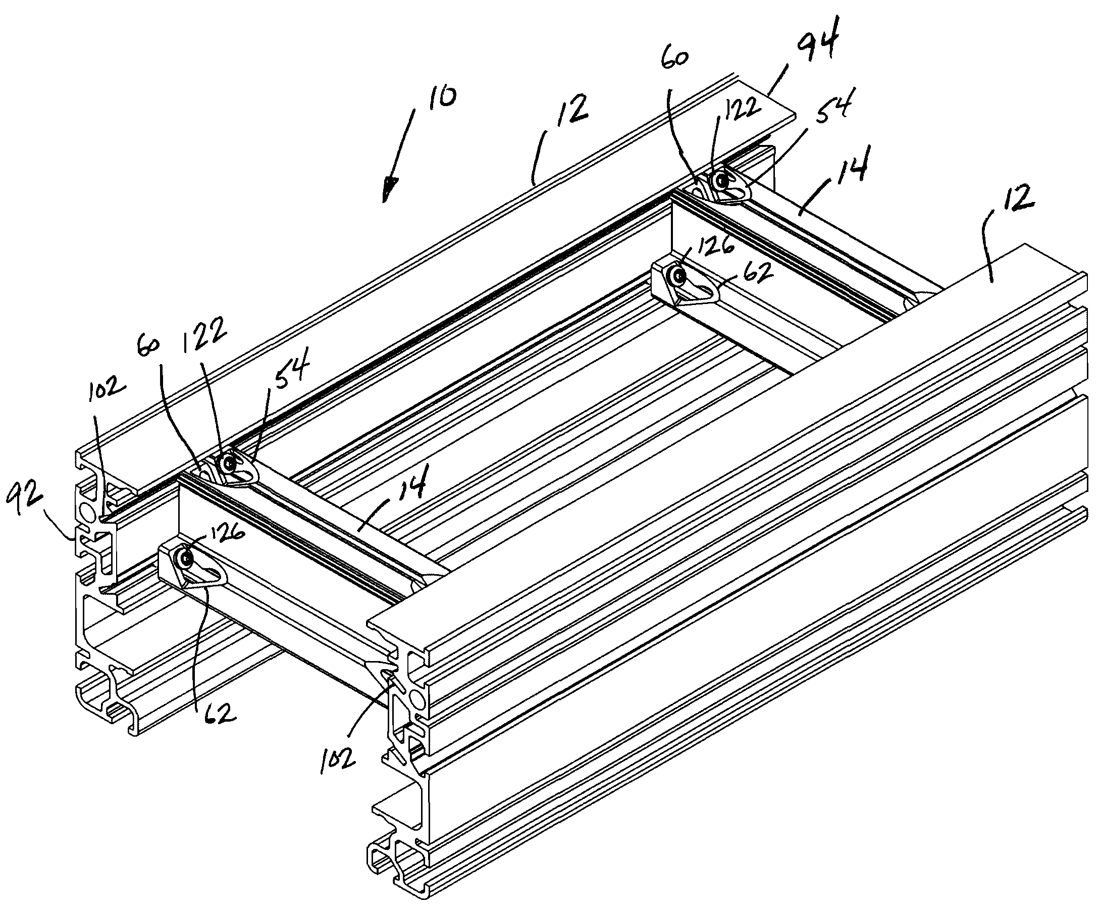
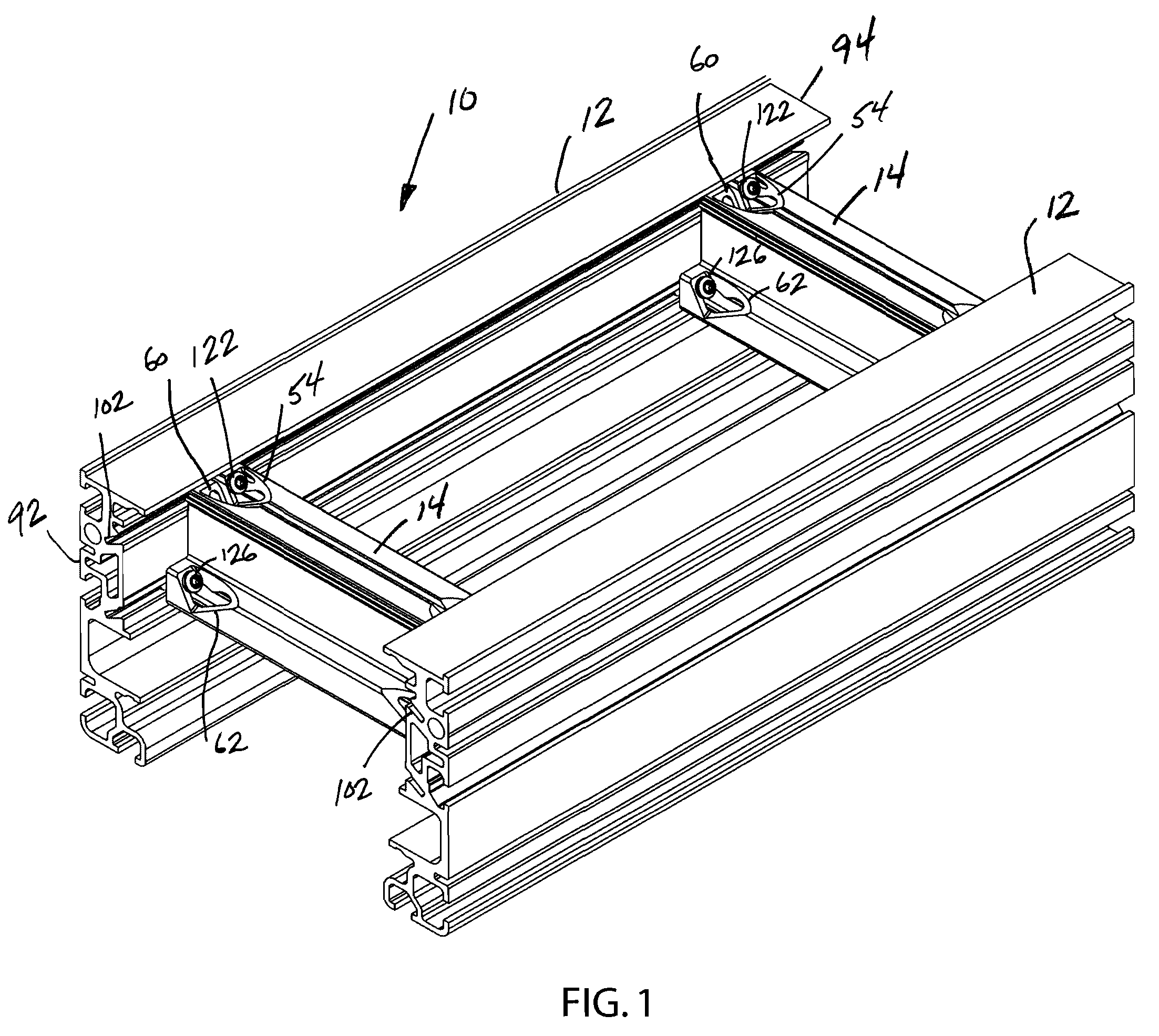
[0022]FIG. 1 illustrates a conveyor frame assembly 10 constructed in accordance with the present invention. The conveyor frame assembly 10 generally includes a pair of side rails 12 spaced from each other by the width of the conveyor belt (not shown) to be utilized with the conveyor frame assembly. The pair of side rails 12 are supported in a spaced relationship by the pair of cross supports 14 illustrated in FIG. 1. Although the conveyor frame assembly 10 shown in FIG. 1 includes only a pair of cross supports 14, it should be understood that additional cross supports 14 could be utilized in conveyor frame assemblies having a significantly greater length and / or width. The cross supports 14 provide structural integrity for the conveyor frame assembly 10 and additional cross supports 14 may be needed for longer lengths of the conveyor frame assembly.

[0023]In the embodiment of the invention illustrated in FIG. 1, both the side rails 12 and the cross supports 14 are formed from extruded...


PUM


Abstract

The present disclosure relates to a conveyor frame assembly that includes a pair of spaced side rails joined by one or more cross supports. Each of the side rails includes a dedicated wire channel and self-contained air flow cavity that enhances the functionality of the conveyor frame assembly. The air flow cavity and the wire channel are formed as part of the side rails separate from typical attachment slots that receive T-shaped connectors. The cross supports utilized with the conveyor frame assembly are attached to the side rails by upper and lower connectors that are each accessible from the top of the conveyor frame assembly. Specifically, the cross support includes a center web and laterally offset attachment webs that allow for easy and convenient construction and field modification of the conveyor frame assembly.

Description

CROSS REFERENCE TO RELATED APPLICATION(S)[0001]The present application is based on and claims priority to U.S. Provisional Patent Application Ser. No. 60 / 892,636 filed on Mar. 2, 2007.BACKGROUND OF THE INVENTION[0002]The present invention generally relates to modular conveyor frame assemblies. More specifically, the present invention relates to a conveyor frame assembly that includes configurable cross supports and side rails having multiple passageways and connector slots formed in the side rails.[0003]Presently, moving belt conveyor systems are utilized in vastly different applications to move products / materials from one location to another in an automated fashion. Since conveyor assemblies are used in vastly different applications, the conveyor assemblies oftentimes include auxiliary devices that function in connection with the conveyor assembly to aid in moving products in a desired fashion. As an example, photo detector eyes and pusher devices are oftentimes mounted to the side...

Claims


Application Information

Patent Timeline
Patent Type & Authority Applications(United States)
IPC IPC(8): B65G21/00
CPCB65G21/06B65G21/02
Inventor HAU, PAULHUNDLEY, LEROYBUDE, CRAIGHOSCH, MICHAELJOHNSON, RYAN
Owner DORNER MFG. CORP.
Why Eureka
Try Eureka