Adaptive Protection Circuit For a Power Amplifier

a protection circuit and power amplifier technology, applied in the direction of single-ended push-pull amplifiers, high-frequency amplifiers, gain control, etc., can solve the problems of load mismatch problems, known mechanisms do not solve the aforementioned problems, damage to the device,

Active Publication Date: 2008-09-04
NXP USA INC
View PDF12 Cites 19 Cited by
  • Summary
  • Abstract
  • Description
  • Claims
  • Application Information

AI Technical Summary

Problems solved by technology

It has been found that load mismatch problems occur, in particular, under both high power conditions and when a high battery voltage is applied to the power amplifier.
The increase of DC current, under load mismatch conditions, is highly undesirable (particularly in a hand-portable environment) as it causes increased power consumption and may over-load the power amplifier transistor device thereby resulting in damage to, or failure of, the device.
Known mechanisms do not solve the aforementioned problems.
For example, voltage limiters do not protect the PA from mismatch conditions that lead to high current.
Furthermore, existing current limiters do not protect efficiently the PA from battery voltage variations under mismatch.
However, the effectiveness of the protection circuit is compromised due to the operational amplifier offset voltage ε1 (comparable to the detected voltage Vdet) and to the variation of Vdet with regard to sensing resistor 130 dispersion.
Furthermore, the complexity of the protection circuit may typically lead to undesirable loop stability issues, due to high loop gain.

Method used


Image

  • Adaptive Protection Circuit For a Power Amplifier
  • Adaptive Protection Circuit For a Power Amplifier
  • Adaptive Protection Circuit For a Power Amplifier

Examples


Embodiment Construction

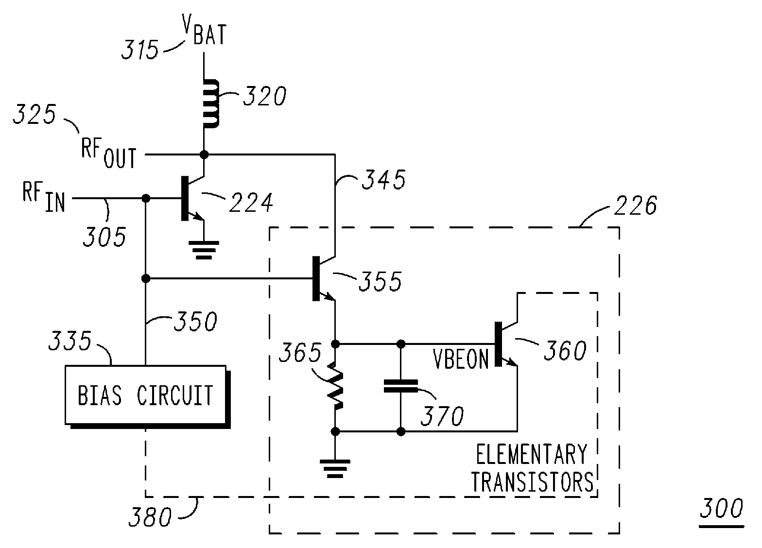
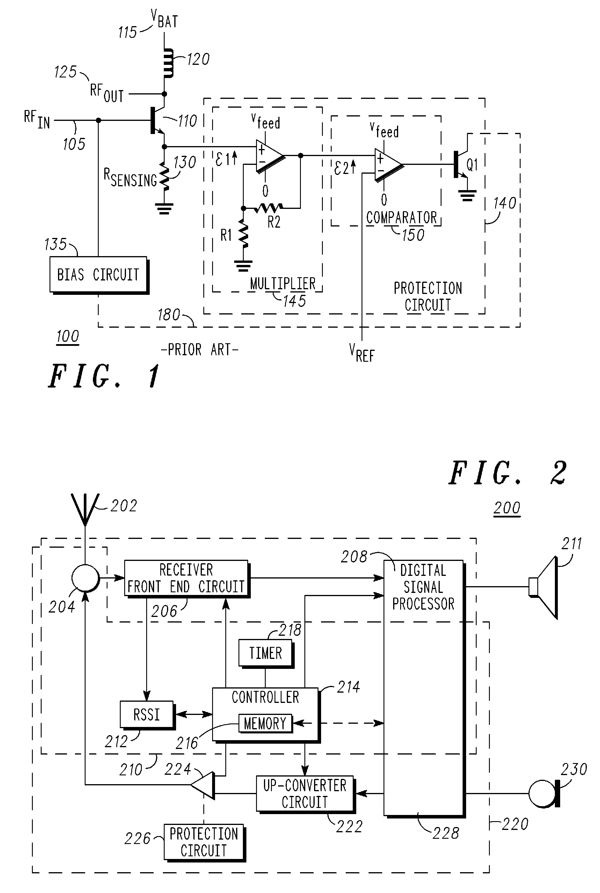
[0018]The preferred embodiment of the present invention will be described with respect to an implementation of a radio frequency (RF) power amplifier (PA) module in a wireless communication unit, such as a mobile phone. However, it will be appreciated by a skilled artisan that the inventive concept herein described may be embodied in any type of RF amplifier unit. In summary, the inventive concept of the present invention proposes a monolithically integrated PA module having a cost and size efficient current limiter, notably indexed to battery voltage, for improving a Power Amplifier's (PA) ruggedness, for example, under extreme VSWR conditions over battery voltage range.

[0019]In a mobile context, in the known prior art, the current threshold or current limit is fixed, as a reference voltage is used for the battery. However, the battery voltage varies. Thus, and as addressed by the inventive concept hereinafter described, it is important to have a current threshold or current limit ...


PUM


Abstract

A radio frequency device comprises a radio frequency (RF) power amplifier (PA) operably coupled to a protection circuit for minimising voltage standing wave ratio effects, wherein the protection circuit comprises a current limiter indexed to a power supplied to the RF PA.In this manner, the protection circuit combines detection of both current and voltage increase in order to provide a direct feedback on the final RF PA stage via a bias control.

Description

FIELD OF THE INVENTION[0001]The preferred embodiment of the present invention relates to a power amplifier (PA) module. The invention is applicable to, but not limited to, an adaptive protection circuit for a wireless communication unit's radio frequency power amplifier arranged to prevent high current effects due to a voltage standing wave ratio (VSWR).BACKGROUND OF THE INVENTION[0002]In the field of radio frequency (RF) power amplifiers (PAs), a PA is typically designed to be ‘matched’ into a 50 ohm load impedance, to ensure efficient power transfer from an RF input signal to an amplified RF output signal. This enables a low power RF input signal to be amplified and a maximum amount of the amplified signal forwarded on to, say, an antenna switch and / or an antenna. In this manner, maximum power transfer is achieved and minimal power is reflected back into the PA output. The reflection back of power is typically due to “load mismatch”, for example where the antenna switch or antenna...

Claims


Application Information

Patent Timeline
Patent Type & Authority Applications(United States)
IPC IPC(8): H03F1/52H03F3/04
CPCH03F1/30H03F2200/78H03F2200/462H03F1/52H03F2200/451H03F2200/477H03F3/19
Inventor KAROUI, WALIDMONTORIOL, GILLESRIONDET, PHILIPPE
Owner NXP USA INC
Why Eureka
Try Eureka