Zoom Lens and Imaging Apparatus

a zoom lens and imaging apparatus technology, applied in the field of zoom lenses and imaging apparatuses, can solve the problem of large blur in images, and achieve the effect of high optical performan

Inactive Publication Date: 2008-09-04
SONY CORP
View PDF3 Cites 21 Cited by
  • Summary
  • Abstract
  • Description
  • Claims
  • Application Information

AI Technical Summary

Benefits of technology

[0025]The invention defined in any one of claims 5 to 8 and claims 13 to 16 satisfies conditional equation (4) given as −5<C5p·ft<−2, where C5p is a curvature (reciprocal of a radius of the curvature) of the most-image-side lens surface of the positive sub lens group disposed in the fifth lens group. Accordingly, the various aberrations occurring in the positive sub lens group of the fifth lens group can be sufficiently compensated for, and high optical performance can be obtained also during the image shift.

Problems solved by technology

However, in an optical system with a high zoom ratio, since the angle of viewing is narrowed in a telephoto end mode, even a small motion blur causes the occurrence of a large blur in the image.
In the conventional motion blur compensation optical systems, the lens group disposed near the aperture diaphragm is shifted, such that interferences tend to occur among a drive mechanism of causing the shifting, a mechanism of opening and closing the aperture diaphragm, and a mechanism of moving the respective lens in the event of, for example, zooming or focusing, so that a lens barrel has to be enlarged in the radial direction.

Method used


Image

  • Zoom Lens and Imaging Apparatus
  • Zoom Lens and Imaging Apparatus
  • Zoom Lens and Imaging Apparatus

Examples


first embodiment

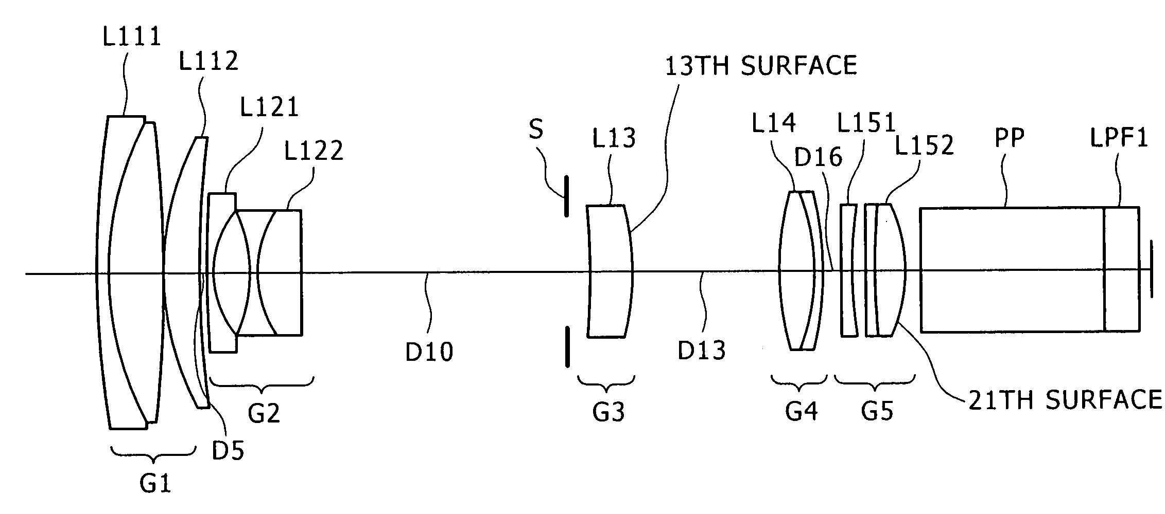
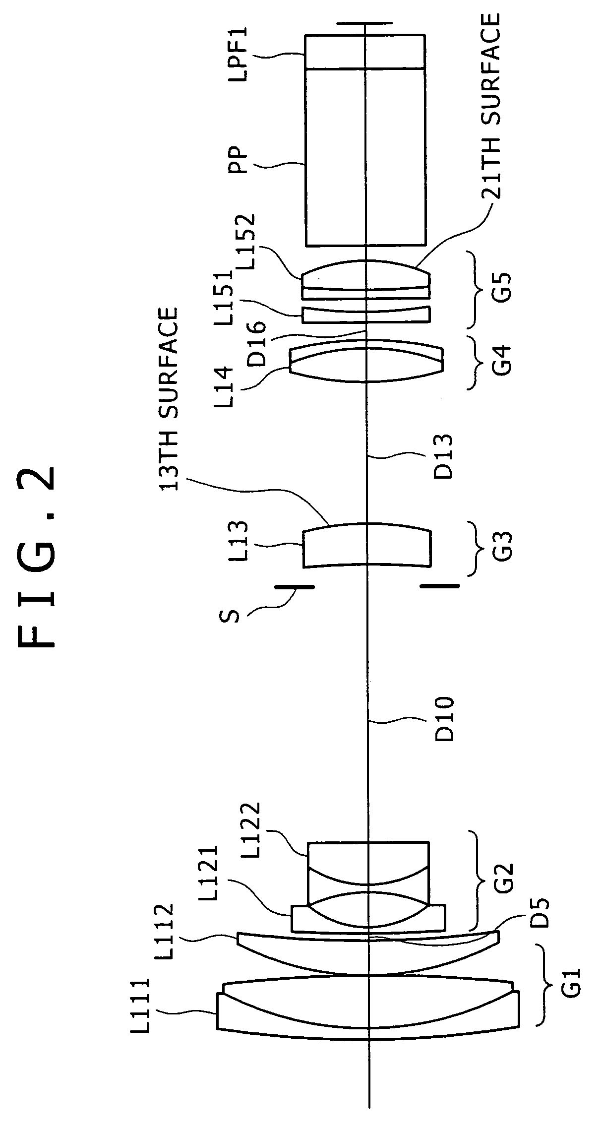
[0086]FIG. 2 shows a lens configuration according to the present inventive zoom lens, in which a first lens group G1 is formed of a cemented lens L111 of a meniscus-shaped negative lens with the convex surface facing the object side, and a positive lens L112 with the convex surface facing the object side; a second lens group G2 is formed of a negative lens L121 with the concave surface facing the image side, and a cemented lens L122 of a both-side concave shaped negative lens and a positive lens with the convex surface facing the object side; a third lens group G3 is formed of a positive meniscus lens L13; a fourth lens group G4 is formed of a cemented positive lens L14 of a both-side convex lens and a meniscus-shaped negative lens with the concave surface facing the object side; and a fifth lens group G5 is formed of a negative lens L151 with the concave surface facing the image side, and a cemented positive lens L152 of a both-side convex lens and a meniscus-shaped negative lens w...

second embodiment

[0097]FIG. 9 shows the lens configuration of the present inventive zoom lens, in which a first lens group G1 is formed of a cemented lens L211 of a meniscus-shaped negative lens with the convex surface facing the object side, and a positive lens L212 with the convex surface facing the object side; a second lens group G2 is formed of a negative lens L221 with the concave surface facing the image side, and a cemented lens L222 of a both-side concave shaped negative lens and a positive lens with the convex surface facing the object side; a third lens group G3 is formed of a negative meniscus lens L231 and a both-side convex lens L232; a fourth lens group G4 is formed of a cemented positive lens L24 of a both-side convex lens and a meniscus-shaped negative lens with the concave surface facing the object side; and a fifth lens group G5 is formed of a both-side concave lens L251 and a both-side convex lens L252.

[0098]In the second embodiment, an aperture diaphragm S is disposed on the obj...

third embodiment

[0108]FIG. 16 shows the lens configuration of the present inventive zoom lens, in which a first lens group G1 is formed of a cemented lens L311 of a meniscus-shaped negative lens with the convex surface facing the object side, and a positive lens L312 with the convex surface facing the object side; a second lens group G2 is formed of a negative lens L321 with the concave surface facing the image side, and a cemented lens L322 of a both-side concave shaped negative lens and a positive lens with the convex surface facing the object side; a third lens group G3 is formed of a negative meniscus lens L331 and a both-side convex lens L332; a fourth lens group G4 is formed of a cemented positive lens L34 of a both-side convex lens and a meniscus-shaped negative lens with the concave surface facing the object side; and a fifth lens group G5 is formed of a both-side concave lens L351 and a both-side convex lens L352.

[0109]In the third embodiment, an aperture diaphragm S is disposed on the obj...


PUM


Abstract

Provided are a zoom lens and an imaging apparatus using the zoom lens, the zoom lens being suited for achieving compactness without increasing the number of lenses and being capable of implementing motion blur compensation. The zoom lens includes lenses arranged in order from an object side into a first lens group having positive refractive power, a second lens group having negative refractive power, a third lens group having positive refractive power, a fourth lens group having positive refractive power, and a fifth lens group having positive refractive power. In the event of a shift of a lens position mode from a wide angle end mode to a telephoto end mode, the first lens group is fixed along an optical axis direction, the second lens group moves to an image side, the third lens group is fixed along the optical axis direction, the fourth lens group compensates for a fluctuation in an image plane position due to the shift of the second lens group, and concurrently moves along the optical axis direction in a close-distance focusing event, and the fifth lens group is fixed along the optical axis direction. An aperture diaphragm is disposed in the vicinity of the third lens group. The fifth lens group includes a negative sub lens group having negative refractive power and a positive sub lens group having a positive refractive power, wherein the image can be shifted in conjunction with a shift of the positive sub lens group in a direction substantially perpendicular to the optical axis. The zoom lens satisfies conditional equation (1) given as 0.6<f5p/Da<1.4, where f5p is a focal distance of the positive sub lens group disposed in the fifth lens group, and Da is a length extending along the optical axis to a paraxial image position from a most-imagewise surface of the positive sub lens group disposed in the fifth lens group.

Description

TECHNICAL FIELD[0001]The present invention relates to a zoom lens and an imaging apparatus, and more specifically, to an imaging apparatus device suited for use with cameras, such as video cameras or digital still cameras that receive light from an imaging device; and the invention relates to a zoom lens and an imaging apparatus that uses the zoom lens suited for motion blur compensation.BACKGROUND ART[0002]Conventionally, methods are known that convert an image of an object (object image) formed on an imaging device plane by using the imaging device that utilizes photoelectric transducers, such as CCDs (charge coupled devices) and CMOSs (complementary metal-oxide semiconductors), and that thereby record the image.[0003]With advancements in microprocessing technology, there have been implemented, for example, processing rate enhancements of central processing units (CPUs) and higher level integration of storage mediums, thereby enabling high speed processing of a large volume of ima...

Claims


Application Information

Patent Timeline
Patent Type & Authority Applications(United States)
IPC IPC(8): G02B27/64G02B15/16
CPCG02B27/646G02B15/173G02B15/145129G02B13/009G02B3/0087G03B17/12H04N23/55
Inventor OHTAKE, MOTOYUKI
Owner SONY CORP
Why Eureka
Try Eureka