Optical multipass cell for repeated passing of light through the same point

Inactive Publication Date: 2008-09-04
MILOSEVIC MILAN +1
View PDF1 Cites 9 Cited by
  • Summary
  • Abstract
  • Description
  • Claims
  • Application Information

AI Technical Summary

Benefits of technology

[0020]FIG. 5 shows a unipoint multipass configuration that can be used to enhance the sensitivity of both reflectance and ATR spectroscopy. The reflecting element 15 placed in a common focal point is either a reflecting sample or a hemispherical ATR element. Several reimaging elements 16 are arranged around the hemisphere with their focal points 17 coincident with the center of curvature of the hemisphere. All the reimaging elements are arranged in a conical configuration around the hemisphere 15 and the common focus 17 is the apex of the co

Problems solved by technology

In some cases the absorption of light or the secondary emitted light are too weak to be reliably measured.
Although the effect is thus magnified, in each of these multiple reflections light interacts with a different portion of the sample requiring a large quantity of the sample for analysis.
This can be a problem in those cases where only a small amount of sample is available.
These cells work well for absorption spectroscopy, but cannot be used to study gasses by Raman or fluorescence spectroscopy.
While the reflectance losses are redu

Method used


Image

  • Optical multipass cell for repeated passing of light through the same point
  • Optical multipass cell for repeated passing of light through the same point
  • Optical multipass cell for repeated passing of light through the same point

Examples


Example

DRAWINGS—REFERENCE NUMERALS

[0023]1 Focal point of a reimaging element[0024]2 Incoming ray[0025]3 First parabolic mirror[0026]3′ Second parabolic mirror[0027]4 Outgoing ray[0028]5 Axis of the two parabolic surfaces[0029]6 First optical reimaging element[0030]7 Second optical reimaging element[0031]8 Focal point of two reimaging element multipass configuration[0032]9 Outgoing ray[0033]10 Incoming ray[0034]11 First reflective parabolic surface[0035]12 Second reflective parabolic surface[0036]13 Spherical entrance / exit surface[0037]14 Focal point of solid reimaging element[0038]15 Hemispherical ATR element[0039]16 Reimaging optical elements[0040]17 Center of hemispherical ATR element[0041]18 Outgoing secondary emitted radiation[0042]20 Cutting plane for parabolic mirrors

DETAILED DESCRIPTION OF THE PREFERRED EMBODIMENTS

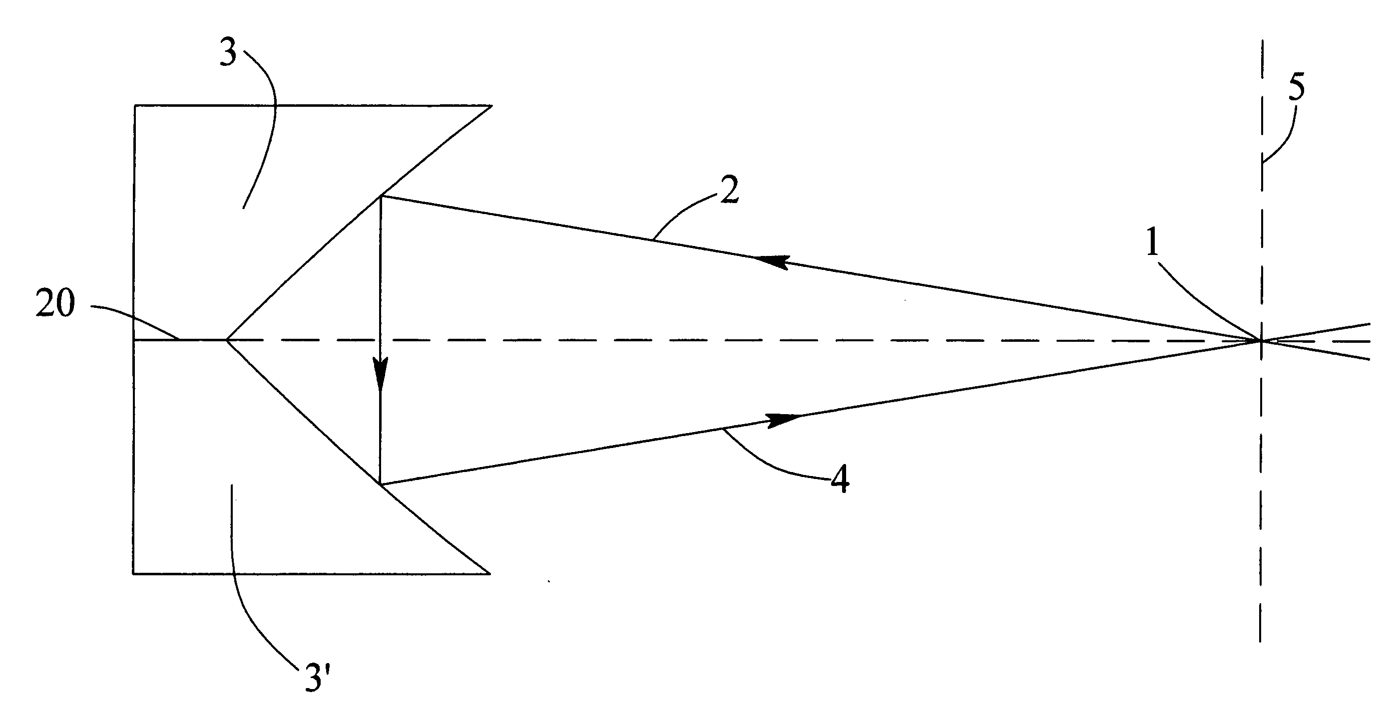
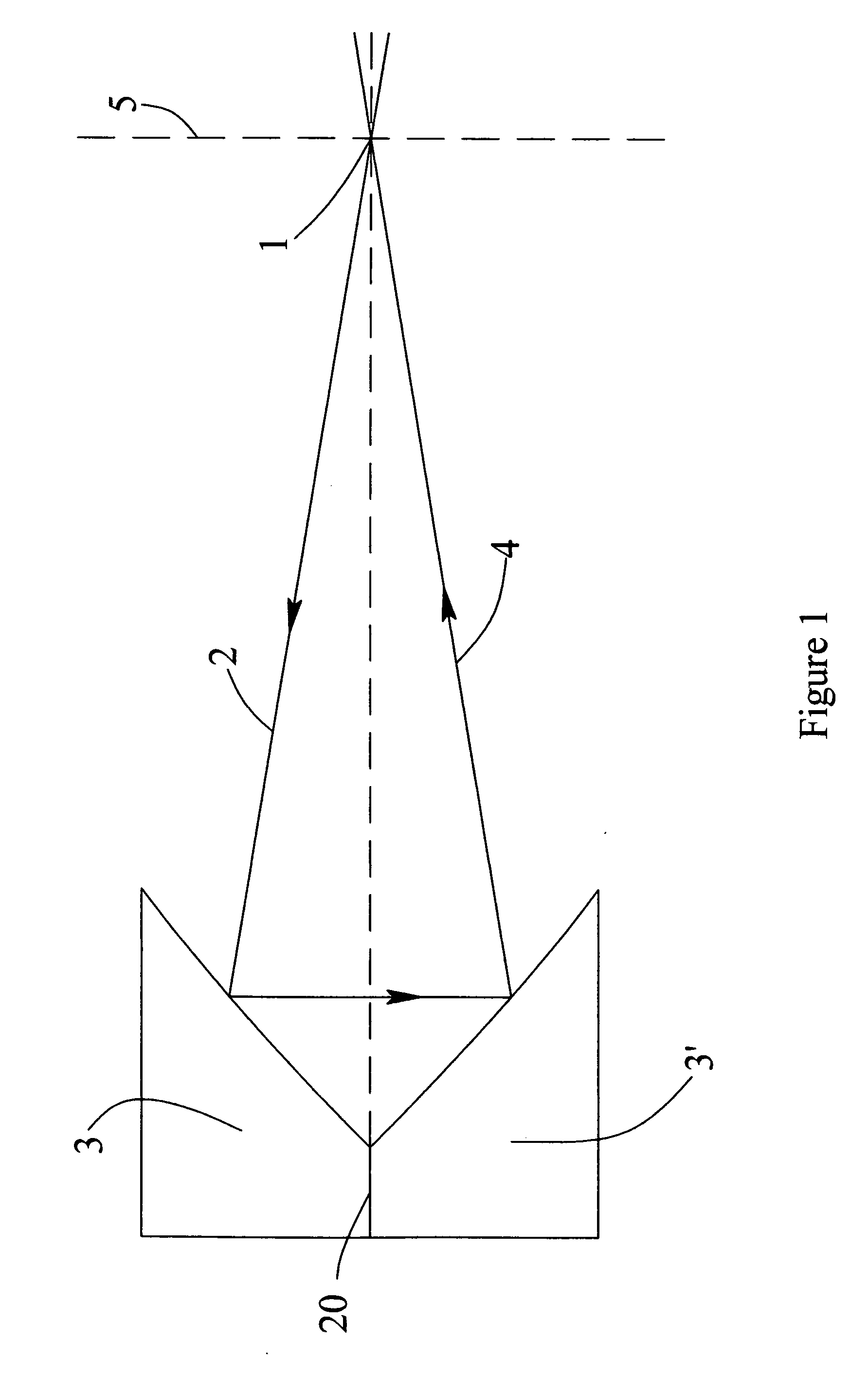
[0043]The optical multipass unipoint cell configurations described herein are based on the special optical property of the optical reimaging element, consisting of two sym...


PUM


Abstract

The present invention is a multipass unipoint optical cell used for the improved analysis of samples by transmission, reflection, Raman or fluorescence spectroscopy by the multiple reimaging of light through the same analysis point. The cell comprises two or more identical optical reimaging elements each consisting of two symmetrically opposing, identical, confocal, and coaxial parabolic reflective surfaces with the property to refocus any ray of light coming from the common focal point onto one of the parabolic surfaces, back to the same focal point by the other parabolic surface at an angle to the incoming ray. Two or more of these reimaging optical elements can be configured around the common focal point to form different multipass unipoint optical cell configurations, all the passes crossing in the analysis point where a sample is brought to interact with light, the effect of said interaction being enhanced in proportion to the number of passes.

Description

CROSS-REFERENCE TO RELATED APPLICATIONS[0001]This application claims the benefit of provisional patent application Ser. No. 60 / 904,225, filed Mar. 1, 2007 by the present inventors and the benefit of provisional patent application Ser. No. 61 / 003,230, filed Nov. 15, 2007 by the present inventors.FEDERALLY SPONSORED RESEARCH[0002]Not ApplicableSEQUENCE LISTING OR PROGRAM[0003]Not ApplicableBACKGROUND[0004]1. Field of the Invention[0005]The field of the present invention relates to optical spectroscopy. Specifically, firstly it relates to the analysis of samples by Raman, transmission, reflection or fluorescence spectroscopy. Secondly, it relates to an optical multipass unipoint cell for the enhancement of said analysis by repeatedly reimaging the light back into the same analysis point. Thirdly, it relates to the special configuration of the reimaging system whereby the reflectance losses are recycled back for analysis thus improving the efficacy of the gain achieved by the multipass ...

Claims


Application Information

Patent Timeline
IPC IPC(8): G02B5/08
CPCG02B17/004
Inventor MILOSEVIC, MILANMILOSEVIC, VIOLET
Owner MILOSEVIC MILAN
Why Eureka
Try Eureka