Heat radiating device for lamp

a heat radiating device and lamp technology, applied in outdoor lighting, semiconductor devices for light sources, lighting and heating apparatus, etc., can solve the problems of poor heat radiation performance, large amount of heat, and accelerate the aging or even failure of led chips, so as to improve heat dissipation efficiency, increase heat dissipation area, and increase heat dissipation efficiency

Inactive Publication Date: 2008-09-04
CHEN BOR JANG
View PDF3 Cites 86 Cited by
  • Summary
  • Abstract
  • Description
  • Claims
  • Application Information

AI Technical Summary

Benefits of technology

[0007]The primary object of the present invention is to provide an improved heat radiating device, characterized in which an exhaust space is configured around the periphery of lamp stand, an exhaust fan is disposed at the top of exhaust space to perform continuous ventilation, and a plurality of heat conductors are provided at the back of the printed circuit board of a light emitting diode (LED) lamp set that extend to the periphery of lamp stand in the exhaust space to enlarge the heat dissipation area. As such, high heat generated by the LED lamp set can be rapidly conducted to the periphery of lamp stand, thereby enhancing the heat dissipation efficiency. At the same time, heat dispersed in the exhaust space can be vented outside rapidly to achieve the effect of rapid heat dissipation.
[0008]Another object of the present invention is to provide a simple looking, easily made, convenient and unconventional improved heat radiating device for lamp that effectively enhances the heat dissipation efficiency of lamp, thereby prolonging its service life, and meeting the criteria of applicability, enablement, and inventive step.

Problems solved by technology

But LED would generate large amount of heat while it illuminates.
If the heat is not dissipated in time, it will accelerate the aging or even the failure of LED chip.
Using the heat sink described above alone for heat dissipation purpose no longer meets the needs and results in poor performance of heat radiation.

Method used


Image

  • Heat radiating device for lamp
  • Heat radiating device for lamp
  • Heat radiating device for lamp

Examples


Embodiment Construction

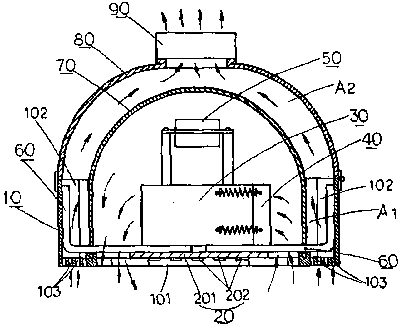
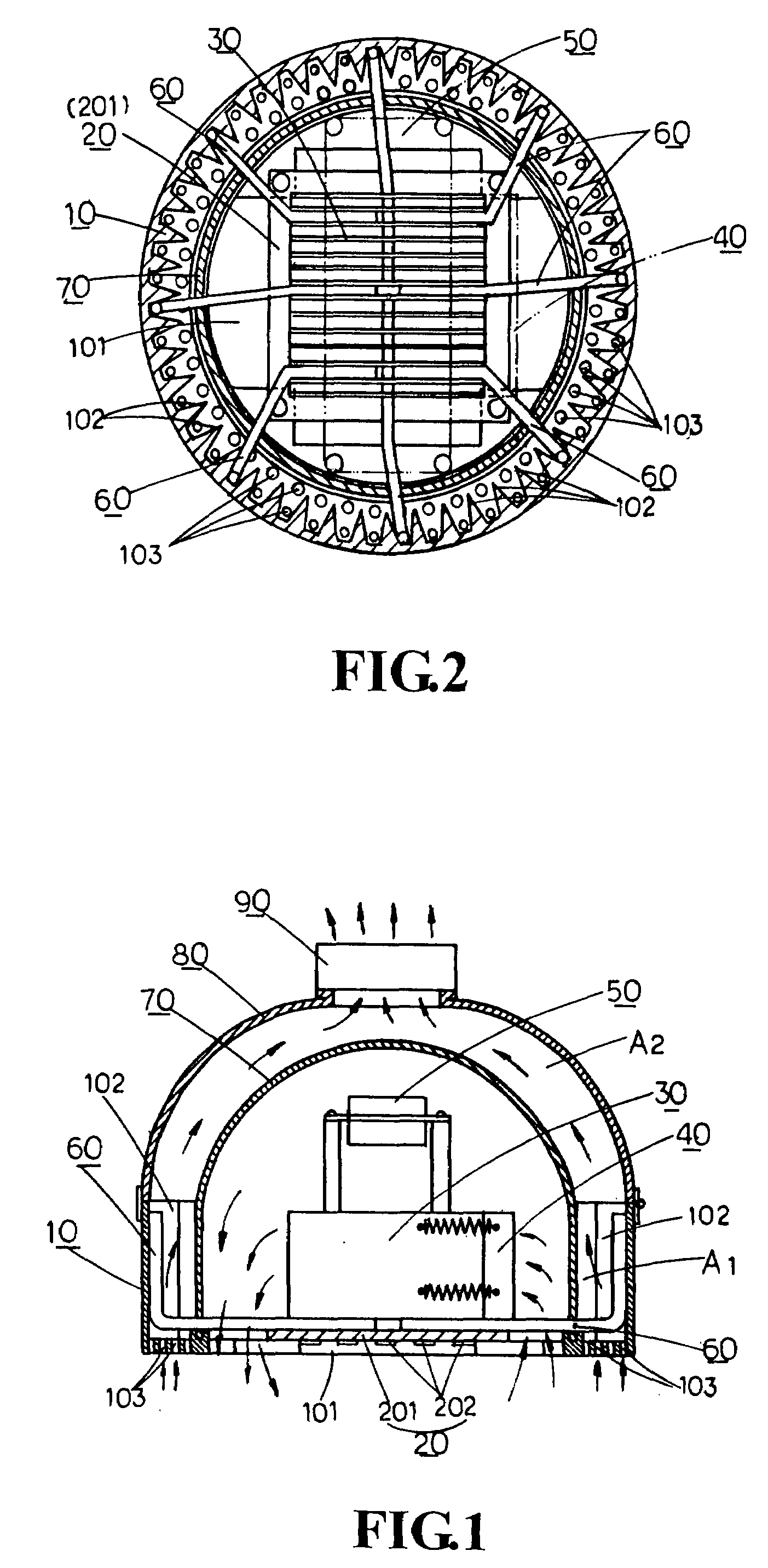
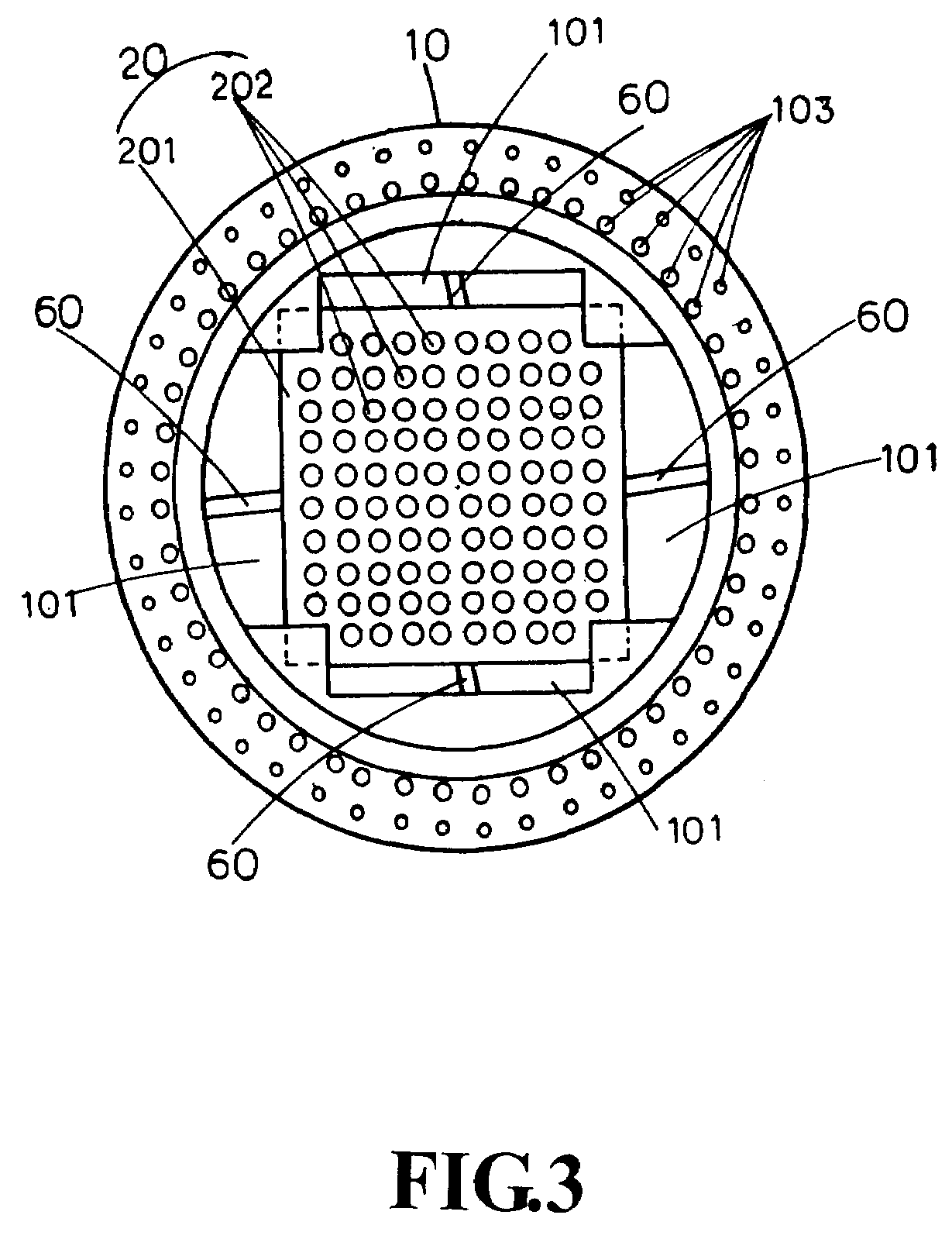
[0014]Referring to FIGS. 1˜4, the improved heat radiating device according to the invention comprises a lamp stand 10 in a generally concave shape and having a large perforated hole 101 at its bottom, disposed with a plurality of heat sinks 102 arranged along its peripheral inner wall, and provided with a plurality of through-going guide holes 103 near its bottom periphery; a light-emitting diode (LED) lamp set 20 arranged at the bottom of lamp stand 10 and provided with a printed circuit board 201 and a plurality of light emitting diodes 202 attached to the printed circuit board 201, the light emitting diodes corresponding exactly to the perforated hole 202 of lamp stand 20; a radiator 30 disposed at the back of printed circuit board 201 of LED lamp set and located inside the lamp stand 10, and provided with a plurality of radiator fins 301 capable of dissipating the heat generated by the LED lamp set 20; a first exhaust fan 40 arranged at one side of radiator 30 and able to discha...


PUM


Abstract

The present invention relates to an improved heat radiating device for lamp, comprising an exhaust space configured around the periphery of lamp stand, an exhaust fan disposed at the top of exhaust space, and simultaneously a radiator and a plurality of heat conductors at the back of the printed circuit board of a light emitting diode (LED) lamp set where the heat conductors extend to the peripheral inner wall of lamp stand in the exhaust space. Through such a radiating device, high heat generated by the LED lamp set can be dissipated through the radiator and through the plurality of heat conductors to the periphery of lamp stand in the exhaust space, thereby enlarging the heat dissipation area. In addition, through the exhaust fan disposed at the top of the exhaust space, ventilation can take place continuously to let the heat in the exhaust space be vented rapidly, thereby achieving fast heat dissipation and prolonging the service life of LED lamp.

Description

BACKGROUND OF THE INVENTION[0001]1. Field of the Invention[0002]The present invention relates to an improved heat radiating device for lamp, more particularly, a heat radiating device for light emitting diode (LED) lamp that features high illuminating efficiency and low power consumption, characterized in which an exhaust space is configured around the periphery of lamp stand, an exhaust fan is disposed at the top of exhaust space to perform continuous ventilation, and a plurality of heat conductors are provided at the back of the printed circuit board of a light emitting diode (LED) lamp set that extend to the periphery of lamp stand in the exhaust space. As such, high heat generated by the LED lamp set can be rapidly conducted to the periphery of lamp stand, thereby enlarging the heat dissipation area. At the same time, heat dispersed in the exhaust space can be vented outside rapidly, thereby achieving fast heat dissipation and prolonging the service life of LED lamp.[0003]2. Des...

Claims


Application Information

Patent Timeline
Patent Type & Authority Applications(United States)
IPC IPC(8): F21V29/02
CPCF21V29/02F21Y2101/02F21W2131/10F21Y2115/10F21V29/00F21V29/74F21V29/677
Inventor CHEN, BOR-JANG
Owner CHEN BOR JANG
Why Eureka
Try Eureka