Steam Turbine and Method for Operation of a Steam Turbine

a steam turbine and steam technology, applied in the field of steam turbines, can solve the problems of significantly more expensive materials, inability to increase the temperature indefinitely, and specific temperature resistance of component parts, etc., and achieve the effect of reducing the capital outlay cost, increasing the efficiency of steam turbines, and increasing the power

Active Publication Date: 2008-09-04
SIEMENS ENERGY GLOBAL GMBH & CO KG
View PDF11 Cites 26 Cited by
  • Summary
  • Abstract
  • Description
  • Claims
  • Application Information

AI Technical Summary

Benefits of technology

[0025]Therefore, the cross-return passage can be especially simply formed with regard to production engineering, which considerably lowers the capital outlay costs.
[0026]In a further advantageous development, an overload inlet, which leads through the outer casing and inner casing, leads into the inflow chamber. During operation of a steam turbine, it is quite customary to temporarily guide additional steam through an overload inlet into the steam turbine in order to achieve greater power as a result of it. By means of the cross-return passage which, just like the overload inlet, leads into the inflow chamber, steam is additionally delivered which altogether leads to an efficiency increase of the steam turbine.

Problems solved by technology

However, especially a temperature increase is not indefinitely possible for material engineering reasons.
The component parts are specifically limited in their resistance to temperature.
Without efficient cooling, significantly more expensive materials (for example, nickel based alloys) would be necessary in the case of increasing temperatures.
However, this has the disadvantage that a temperature difference over the inner casing wall must remain limited since otherwise with too great a temperature difference the inner casing would be too severely thermally deformed.
By this, however, only a very limited cooling action for the casing can be achieved.
In the center hollow bore of the rotor which: is provided for this, however, increased centrifugal force stresses are to be taken into account, which represents a considerable disadvantage in design and operation.
However, this is limited to the main flow region of the working medium and is still worthy of improvement.
During a loading of conventional steam turbines with higher steam parameters, this can lead to an increased thermal loading which affects the whole turbine, which could be only inadequately reduced by means of a customary cooling of the casing which is described above.
In this case, there is the problem that during the use of hitherto customary turbine materials, the increasing stress of the steam turbine body as a result of increased steam parameters, for example according to the “Neft” article, can lead to a disadvantageous thermal loading of the steam turbine.
Consequently, a production of this steam turbine is hardly possible anymore.

Method used


Image

  • Steam Turbine and Method for Operation of a Steam Turbine
  • Steam Turbine and Method for Operation of a Steam Turbine
  • Steam Turbine and Method for Operation of a Steam Turbine

Examples


Embodiment Construction

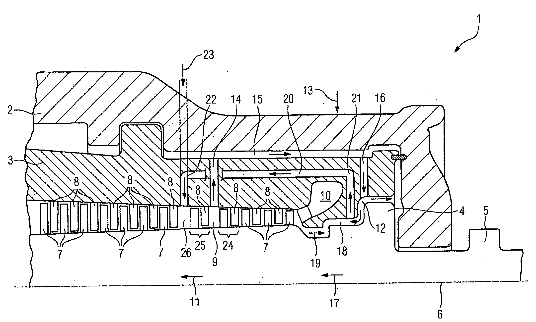
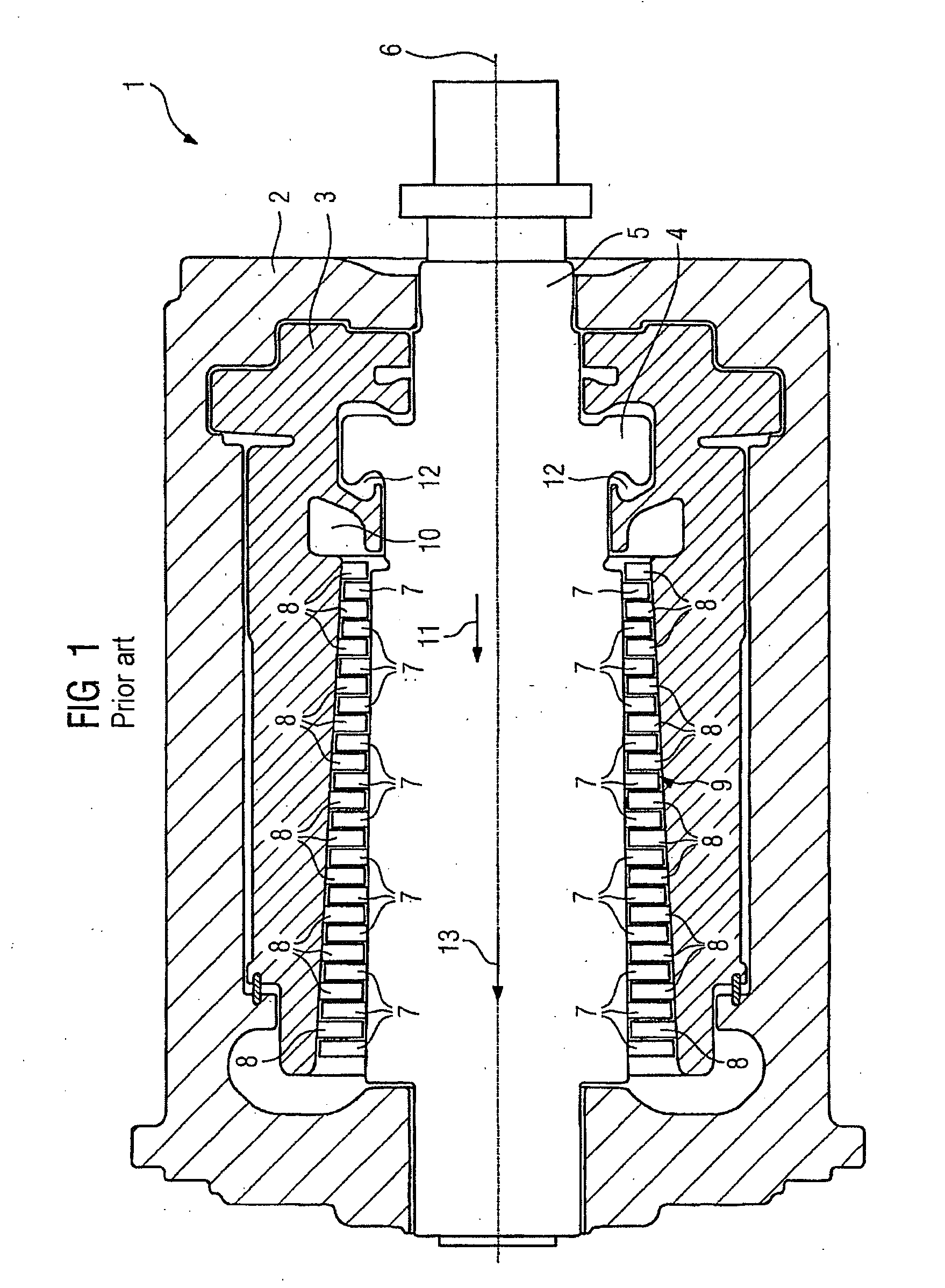
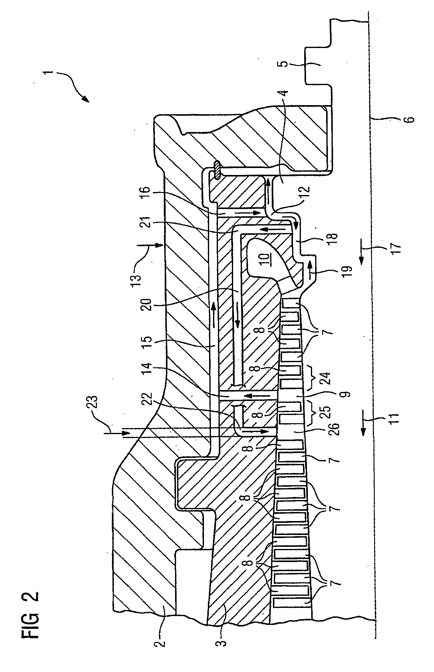
[0037]A cross section through a steam turbine 1 according to the prior art is shown in FIG. 1. The steam turbine 1 has an outer casing 2 and an inner casing 3. The inner casing 3 and the outer casing 2 have a live steam feed duct, which is not shown in detail. A rotor 5, which has a thrust balance piston 4, is installed inside the inner casing 3 in a rotatably mounted manner. The rotor is customarily formed rotationally symmetrically around a rotational axis 6. The rotor 5 comprises a plurality of rotor blades 7. The inner casing 3 has a plurality of stator blades 8. A flow passage 9 is formed between the inner casing 3 and the rotor 5. A flow passage 9 comprises a plurality of blade stages which in each case are formed from a row of rotor blades 7 and a row of stator blades 8.

[0038]Live steam flows through the live steam feed duct into an inlet opening 10 and from there flows in a flow direction 11 through the flow passage 9 which extends basically parallel to the rotational axis 6...


PUM


Abstract

Disclosed is a steam turbine comprising an exterior housing and an interior housing. The exterior housing and the interior housing are provided with a fresh steam supply duct. A rotor that encompasses several impeller blades and a thrust-compensating piston is rotably mounted within the interior housing. Said interior housing is equipped with several guide blades that are disposed such that a flow duct comprising several blade stages, each of which comprises a series of impeller blades and a series of guide blades, is formed along a specific direction of flow. The interior housing is further equipped with a recirculation duct which is embodied as a pipe that communicates between a space located between the interior housing and the exterior housing and the flow duct downstream of a blade stage. The interior housing is additionally equipped with a supply duct that is configured as a pipe which communicates between the space located between the interior housing and the exterior housing and an antechamber of the thrust-compensating piston located between the thrust-compensating piston of the rotor and of the interior housing.

Description

CROSS REFERENCE TO RELATED APPLICATIONS[0001]This application is the US National Stage of International Application No. PCT / EP2005 / 053375, filed Jul. 14, 2005 and claims the benefit thereof. The International Application claims the benefits of European application No. 04018285.9 filed Aug. 2, 2004, both of the applications are incorporated by reference herein in their entirety.FIELD OF INVENTION[0002]The invention relates to a steam turbine with an outer casing and an inner casing, wherein the outer casing and the inner casing have a live steam feed duct, wherein a rotor, which has a thrust balance piston and which comprises a plurality of rotor blades, is installed in a rotatably mounted manner inside the inner casing, and the inner casing has a plurality of stator blades which are arranged in such a way that a flow passage, with a plurality of blade stages which in each case has a row of rotor blades and a row of stator blades, is formed along a flow direction.[0003]Furthermore, t...

Claims


Application Information

Patent Timeline
Patent Type & Authority Applications(United States)
IPC IPC(8): F01D3/00F01D5/06
CPCF01D3/04
Inventor DEIDEWIG, FRANKKOSTENKO, YEVGENMYSCHI, OLIVERWECHSUNG, MICHAELZANDER, UWE
Owner SIEMENS ENERGY GLOBAL GMBH & CO KG
Why Eureka
Try Eureka