

Planar electroporation apparatus and method
a technology of electroporation apparatus and electrode set, which is applied in the direction of specific use of bioreactor/fermenter, enzymology, after-treatment of biomass, etc., can solve the problems of complex cleaning process of elaborate electrode set, damage to many cells, micro-injection,
- Summary
- Abstract
- Description
- Claims
- Application Information
AI Technical Summary
Benefits of technology
Problems solved by technology
Method used
Image

Examples
Embodiment Construction
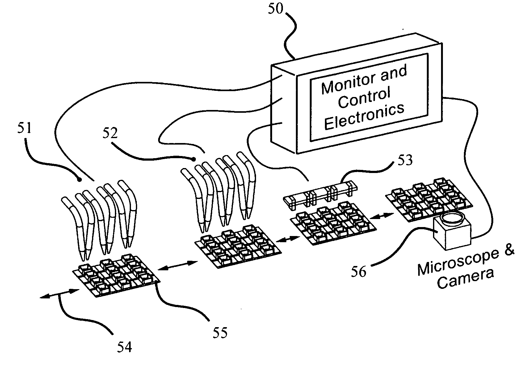
[0044]Previous electroporation devices suffer from drawbacks including the inability to observe cells before, during, and / or after electroporation without disturbing the cells, the inability to electroporate large numbers of cells, and the inability to control electroporation within a population of cells in the electroporation device.
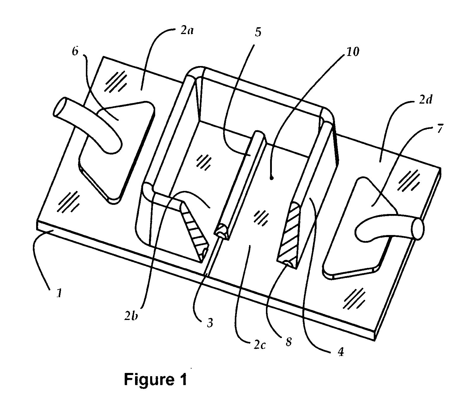
[0045]The invention seeks to overcome such drawbacks of previous devices by providing an electroporation apparatus having planar electrodes and a dielectric barrier disposed between the planar electrodes for controlling the electric field and thereby controlling electroporation of cells. Insofar as planar arrangement of electrodes has been incorporated in previous devices, such devices are either high throughput arrays that do not allow for observation of cells (e.g., U.S. Pat. No. 6,352,853 to King et al.), or have interdigitated electrode arrangements for electrotransformation of individual cells (e.g., U.S. Pat. No. 5,137,817 to Busta et al.) or for ...
PUM
| Property | Measurement | Unit |
|---|---|---|
| barrier height | aaaaa | aaaaa |
| surface resistivity | aaaaa | aaaaa |
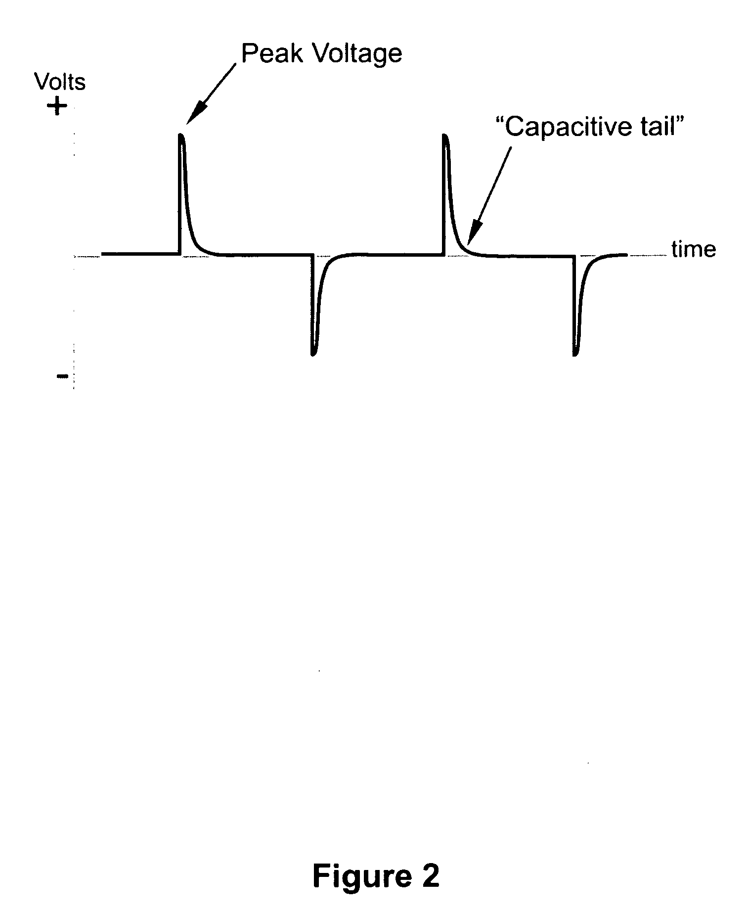
| voltage | aaaaa | aaaaa |
Abstract
Description
Claims
Application Information