Medical guide wire

Inactive Publication Date: 2008-09-04
ASAHI INTECC CO LTD
View PDF6 Cites 27 Cited by
  • Summary
  • Abstract
  • Description
  • Claims
  • Application Information

AI Technical Summary

Benefits of technology

[0016]The stranded wire elements permit the wire elements to relatively slide slightly each other to insure a positional freedom, thus making it possible to restrain strains to appear on an outer surface

Problems solved by technology

This renders the supportability of the guide wire insufficient at 100-200 mm from the distal end of the core line upon holding the catheter and other related equipments inserted into t

Method used


Image

  • Medical guide wire
  • Medical guide wire
  • Medical guide wire

Examples


first embodiment

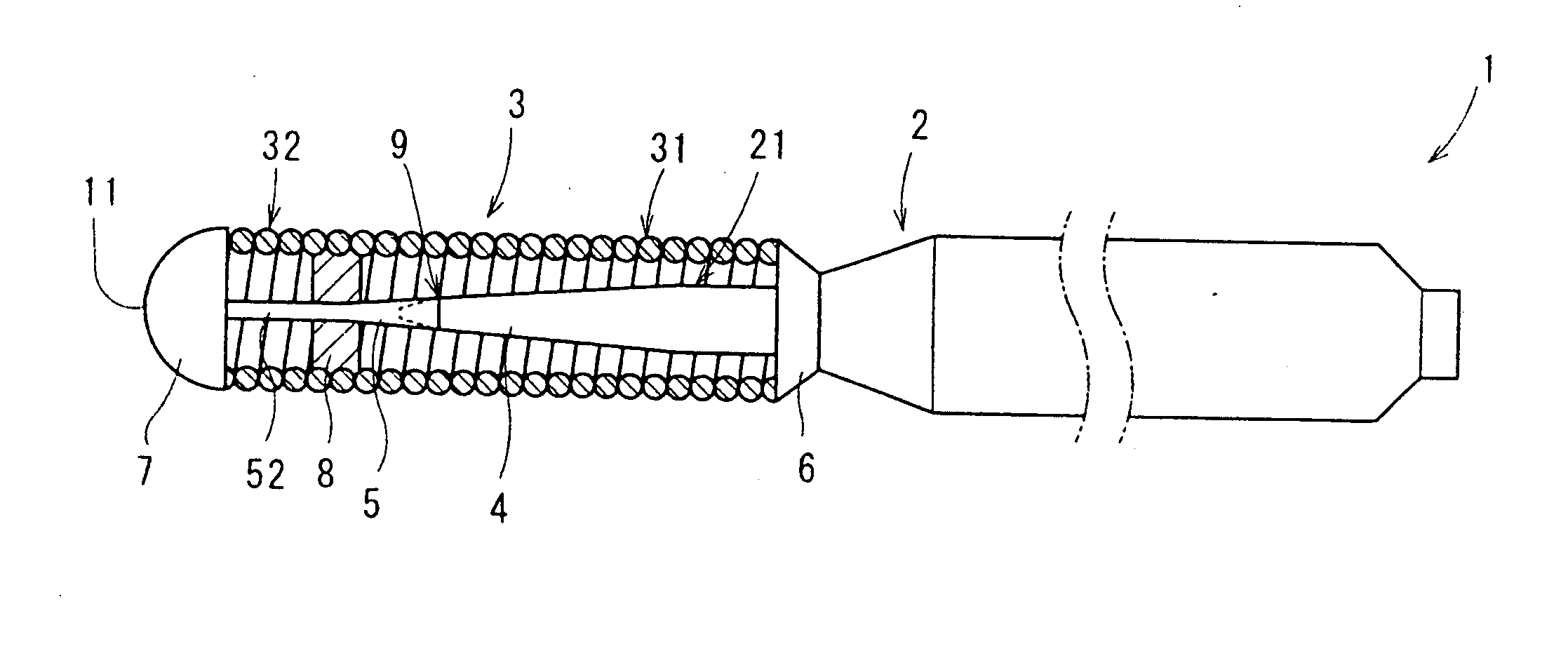
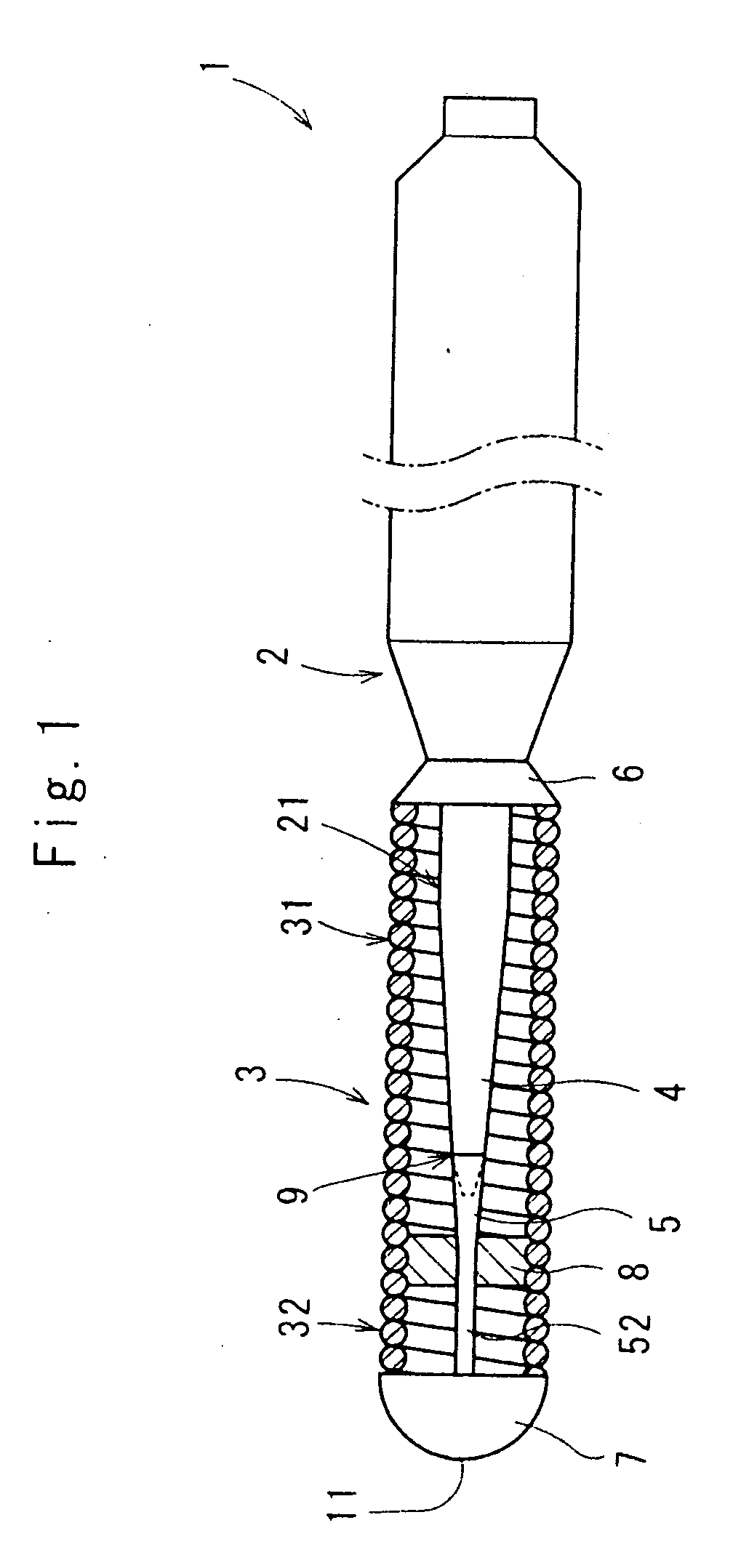
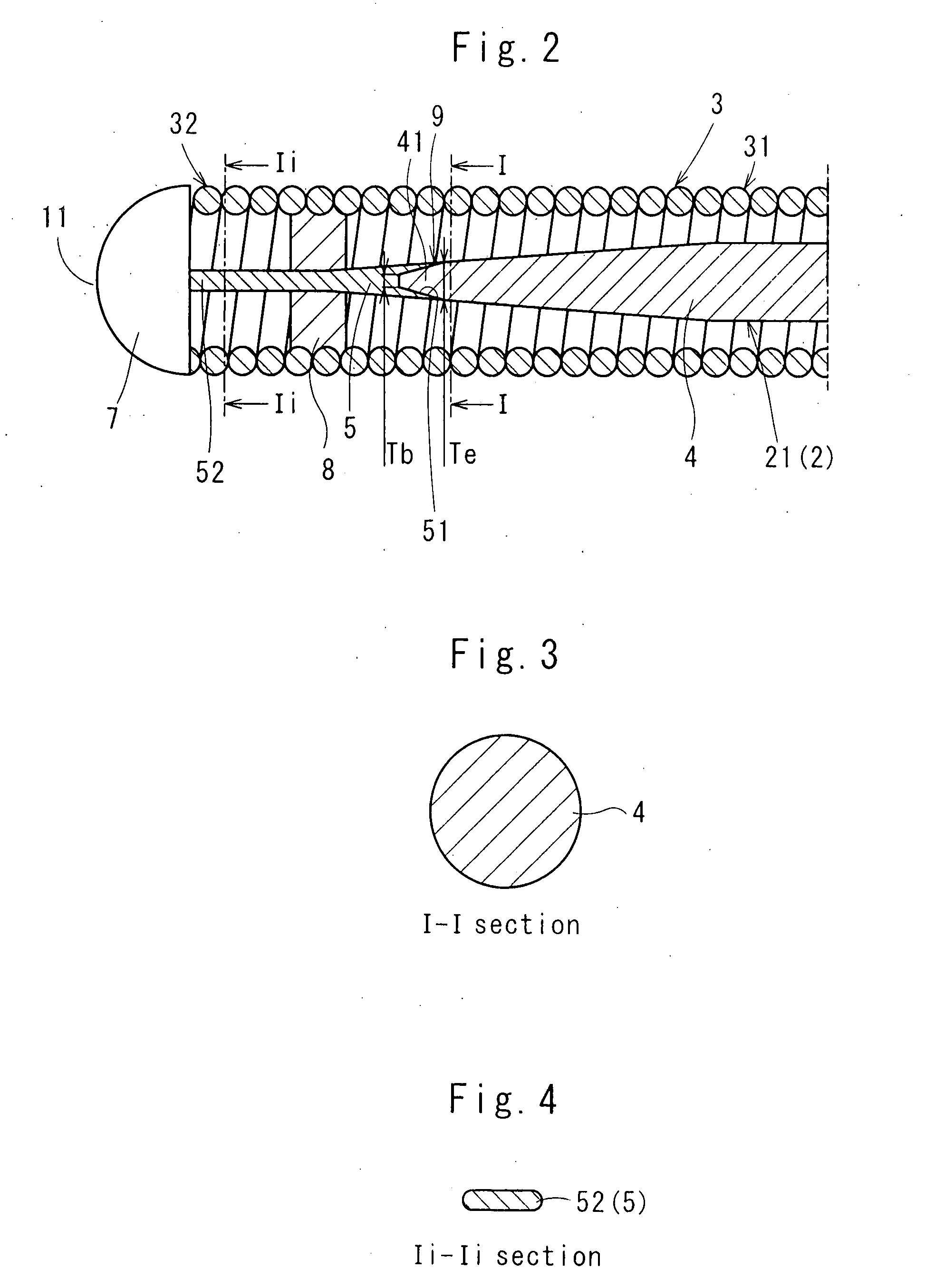
[0036]Referring to FIGS. 1 through 4 which show a medical guide wire 1 (abbreviated merely as “guide wire 1” hereinafter) according to the invention, the right hand side of the drawings is a proximal side, and the left hand side of the drawings is a distal side of the guide wire 1.

[0037]As shown in FIGS. 1, 2, the guide wire 1 has a core line 2 and a helical body 3 placed around a distal end portion 21 of the core line 2 as a flexible sheath body.

[0038]The core line 2 has a distal end portion tapered off so that the distal end portion diametrically decreases progressively as approaching forward. The core line 2 has a proximal side wire 4 and a distal side wire 5, the latter of which is to be bonded to a distal end of the proximal side wire 4. The distal side wire 5 is smaller in rigidity and superior in restitution (anti-kink property) than the proximal side wire 4. The proximal side wire 4 is circular in cross section as shown in FIG. 3.

[0039]By way of illustration, the proximal si...

second embodiment

[0056]In the invention, the distal side wire 5 of the guide Wire 1 is stranded wires as shown in FIGS. 5-7. Namely, the distal side wire 5 has five wire elements with four side wires 55 stranded around one thin core wire 54. The side wires 55 are thicker than the thin core wire 54 with both the wires 54, 55 made of high tensile strength stainless steel. Instead of the five wire elements, three wire elements 56 may be used as shown in FIGS. 8, 9.

[0057]For the five wire elements, the thin core wire 54 measures 0.03-0.04 mm in outer diameter, and the side wire 55 measures 0.06-0.08 mm in outer diameter. For the three wire elements 56, each of the wire elements 56 measures 0.08-0.10 mm in outer diameter with an outer diameter of the stranded wires constituted preferably as 0.15-0.20 mm in terms of a good flexibility and restitution.

[0058]The reason why the structure of the stranded wires (consisting of 2-3 wire elements) is preferable, is explained below in reference to FIGS. 10, 11.

[00...


PUM


Abstract

In a guide wire (1), a core line (2) has a proximal side wire (4) and a distal side wire (5), the latter of which is to be connected to a front end of the proximal side wire (4). The distal wire (5) is smaller in rigidity and superior in restitution than the proximal side wire (4). A concave portion (51) is provided on either the distal end surface of the proximal side wire (4) or a proximal end surface of the distal side wire (5). A convex portion (41) is provided on the other side wire among the distal end surface of the proximal side wire (4) and the proximal end surface of the distal side wire (5) The concave portion (51) and the convex portion (41) are interfit together, and pressure bonded by means of swaging or drawing procedure. This enables a manufacturer to sufficiently bond the distal side wire (5) and the proximal side wire (4) at a portion terminated in less than 100 mm from a distal end (11) of the guide wire (1), thus imparting a good restitution to the distal end (11) with a good supportability and torque-transmission maintained respectively.

Description

BACKGROUND OF THE INVENTION[0001]1. Field of the Invention[0002]The invention relates to a medical guide wire used upon inserting a medical device or equipment (e.g., catheter) into a somatic cavity.[0003]2. Description of Prior Art[0004]Various types of wires have been used to introduce a catheter for the purpose of vascular examination and treatment so that the guide wires are inserted into a target area of a somatic cavity prior to inserting the catheter.[0005]Among the guide wires, one guide wire has a core line which is tapered off to form a cone-shaped configuration, and having a sheath body which is placed around a distal end portion of the core line. Some guide wires have a synthetic resin film coated on an outer surface of the core line.[0006]In order to smoothly advance the guide wire through an arcuate area of the somatic cavity upon introducing the catheter, physical properties required for the guide wire are a good torque-transmission and supportability to hold the cath...

Claims


Application Information

Patent Timeline
IPC IPC(8): A61M25/09
CPCA61M25/09A61M2025/09175A61M2025/09083A61M25/01
Inventor MIYATA, NAOHIKONISHIUCHI, MAKOTOSUGIMURA, HIROO
Owner ASAHI INTECC CO LTD
Why Eureka
Try Eureka