Apparatus and Method For Controlling Internal Combustion Engine

a technology of internal combustion engine and apparatus, which is applied in the direction of machines/engines, non-mechanical valves, output power, etc., can solve the problems of inability to detect the actual crank angle, the discrepancy between the counter and the actual crank angle after installation, and the inability to install an additional crank position sensor. to achieve the effect of improving the starting performance of the engine and ensuring detection

Inactive Publication Date: 2008-09-04
TOYOTA JIDOSHA KK
View PDF9 Cites 11 Cited by
  • Summary
  • Abstract
  • Description
  • Claims
  • Application Information

AI Technical Summary

Benefits of technology

[0011]Accordingly, it is an objective of the present invention to provide an apparatus and a method for controlling an internal combustion engine, which apparatus and method readily detect the occurrence of reverse rotation of the engine without an additional sensor, and reliably match the counter at the stopping of the crankshaft with the actual crank angle, thereby improving the starting performance of the engine in the subsequent engine operation.

Problems solved by technology

However, when the engine is stopped, after the stop of fuel injection and ignition, the engine speed is gradually reduced by rotational resistance due to the pressure in combustion chambers in the compression stroke.
Thus, if the counter is simply incremented at every output of the crank signal, a discrepancy occurs between the counter and the actual crank angle after the reverse rotation takes place.
However, since this configuration for detecting reverse rotation requires two crank position sensors, the installation of an additional crank position sensor is inevitably troublesome and costly.
That is, the implementation of the measure is delayed due to the time lag.
As a result, a discrepancy corresponding to the delay of the implementation remains between the counter and the actual crank angle even after implementing the measure.
Accordingly, it is difficult to match the value of the counter at the time of stopping of the crankshaft with the actual crank angle.
As a result, the first fuel injection and ignition after initiating the starting of the engine cannot be executed at an appropriate time (crank angle).
The starting performance of the engine therefore cannot be improved.

Method used


Image

  • Apparatus and Method For Controlling Internal Combustion Engine
  • Apparatus and Method For Controlling Internal Combustion Engine
  • Apparatus and Method For Controlling Internal Combustion Engine

Examples


Embodiment Construction

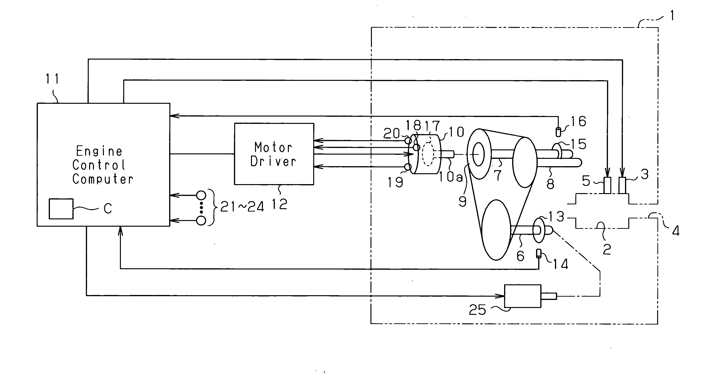
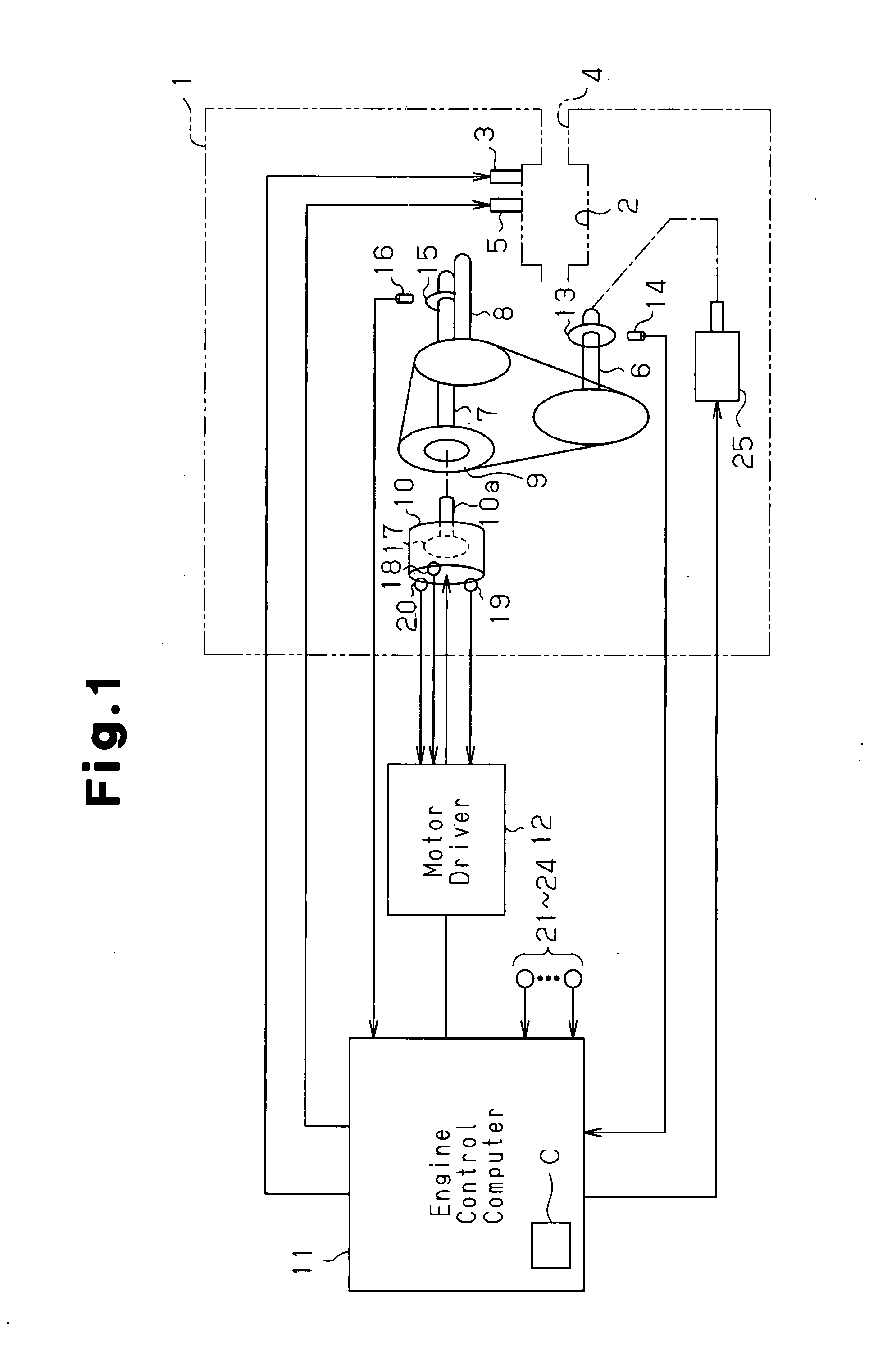
[0036]An automobile multi-cylinder engine 1 according to a preferred embodiment of the present invention will now be described with reference to FIGS. 1 to 22.

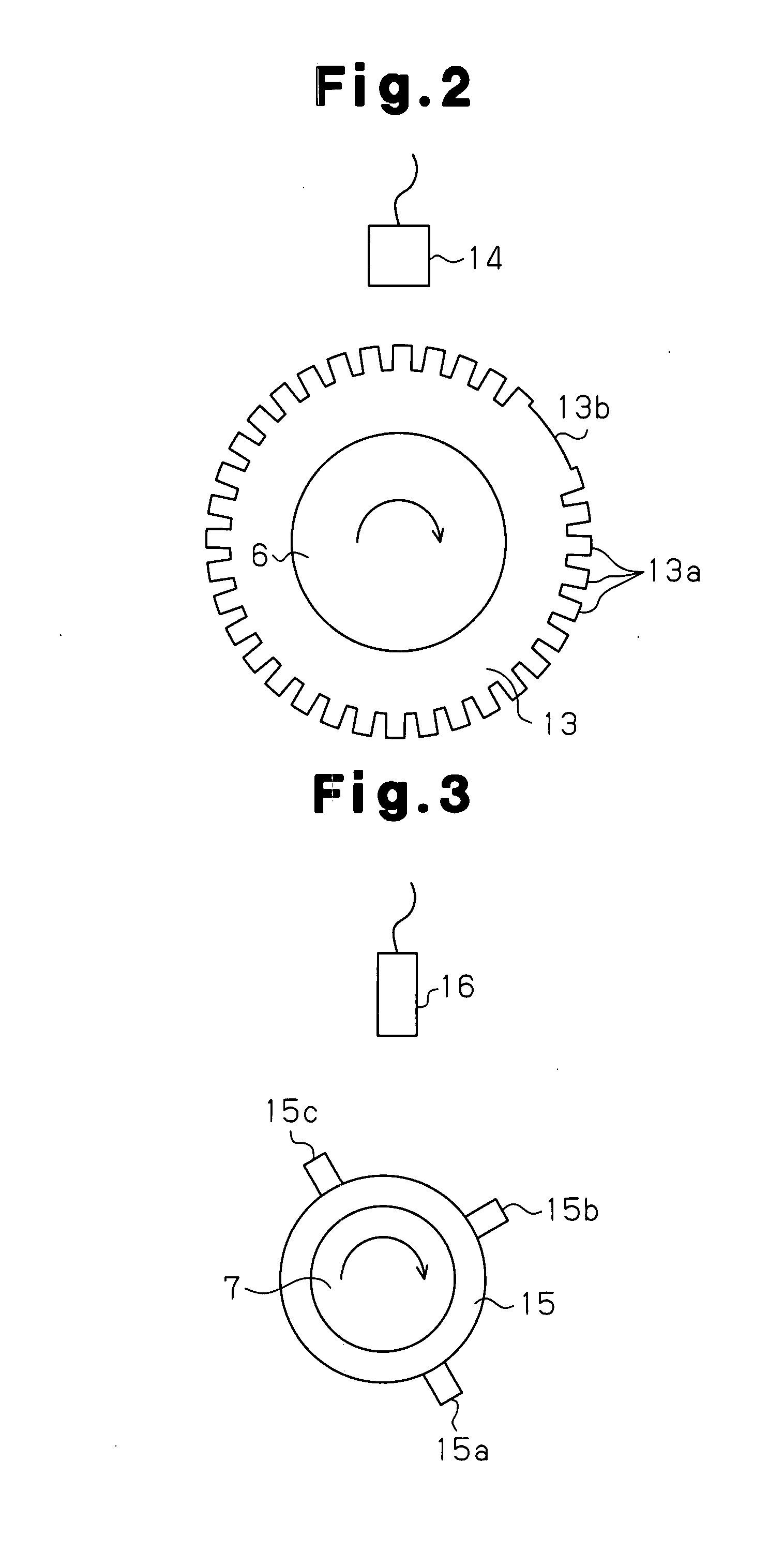
[0037]As shown in FIG. 1, the engine 1 has combustion chambers 2 (only one is shown) into each of which fuel is injected from a fuel injection valve 3. Also, air is drawn into each combustion chamber 2 from an intake passage 4. The air-fuel mixture in each combustion chamber 2 is ignited by an ignition plug 5. When such ignition of air-fuel mixture occurs so that the air-fuel mixture is burned, the combustion energy drives engine 1, in other words, rotates a crankshaft 6. A starter 25 is connected to the crankshaft 6. The starter 25 forcibly rotates the crankshaft 6 when starting the engine 1 (cranks the engine 1).

[0038]Rotation of the crankshaft 6 is transmitted to an intake camshaft 7 and an exhaust camshaft 8. The rotation transmitted from the crankshaft 6 causes the camshafts 7, 8 to rotate 360° per 720° rotation of the cr...


PUM


Abstract

A variable valve timing mechanism 9 includes an electric motor 10 coupled to an intake camshaft 7. A plurality of rotation sensors 18 to 20 are located about the rotor 17 of the electric motor 10. Each of the sensors 18 to 20 outputs a signal corresponding to induced voltage generated by rotation of the rotor 17. Based on the signals form the rotation sensors 18 to 20, reverse rotation of an engine is detected. A counter C is decremented every time a crank signal is output after the occurrence of reverse rotation is detected. Further, a subtraction value Y is computed that corresponds to a discrepancy between the counter C and the actual crank angle caused by a discrepancy between the actual point in time of the occurrence of reverse rotation and the point in time of the detection of the reverse rotation. The counter C is reduced by the subtraction value Y. As a result, reverse direction of the engine is readily detected without providing a dedicated sensor, and the counter is reliably caused to correspond to the actual crank angle.

Description

TECHNICAL FIELD[0001]The present invention relates to an apparatus and a method for controlling an internal combustion engine.BACKGROUND ART[0002]In an internal combustion engine such as an automobile engine, the crank angle is acquired based on a crank signal and a cam signal. Based on the crank angle, fuel injection and ignition are performed (refer to Japanese Laid-Open Patent Publication No. 8-144825).[0003]The crank signal is output by a crank position sensor located in the vicinity of a crank rotor attached to the crankshaft as the crankshaft rotates, for example, at every 30° of crank angle. The profile of the crank rotor is shaped such that the crank signal at equal intervals is output from the crank position sensor. On the other hand, the cam signal is output by a cam position sensor located in the vicinity of a cam rotor attached to a camshaft as the camshaft rotates at every 360° rotation of the camshaft (720° of crank angle). The profile of the cam rotor is shaped such t...

Claims


Application Information

Patent Timeline
Patent Type & Authority Applications(United States)
IPC IPC(8): F02D35/02G01M15/06F01L1/344F16D3/10F02D13/02F02D45/00F02P7/067
CPCB60W10/06Y02T10/46F01L1/344F01L1/352F01L13/02F01L2001/0537F01L2009/0411F01L2800/03F01L2820/041F01L2820/042F02D37/02F02D41/009F02D41/06F02D2041/0095F02D2250/06F02P5/1506G01M15/06B60W20/00Y02T10/40F01L9/22
Inventor NAKAMURA, MUNENORI
Owner TOYOTA JIDOSHA KK
Why Eureka
Try Eureka