Hash table operations with improved cache utilization

a technology of cache utilization and cache utilization, applied in the field of data organizing methods and apparatuses, can solve the problems of amortization of costs, and achieve the effect of reducing memory bandwidth, reducing memory bandwidth, and increasing locality and consequently processor cache utilization

a technology of cache utilization and cache utilization, applied in the field of data organizing methods and apparatuses, can solve the problems of amortization of costs, and achieve the effect of reducing memory bandwidth, reducing memory bandwidth, and increasing locality and consequently processor cache utilization

US20080215849A1Inactive Publication Date: 2008-09-04CERTEON

Image

  • Hash table operations with improved cache utilization
  • Hash table operations with improved cache utilization
  • Hash table operations with improved cache utilization

Examples


Embodiment Construction

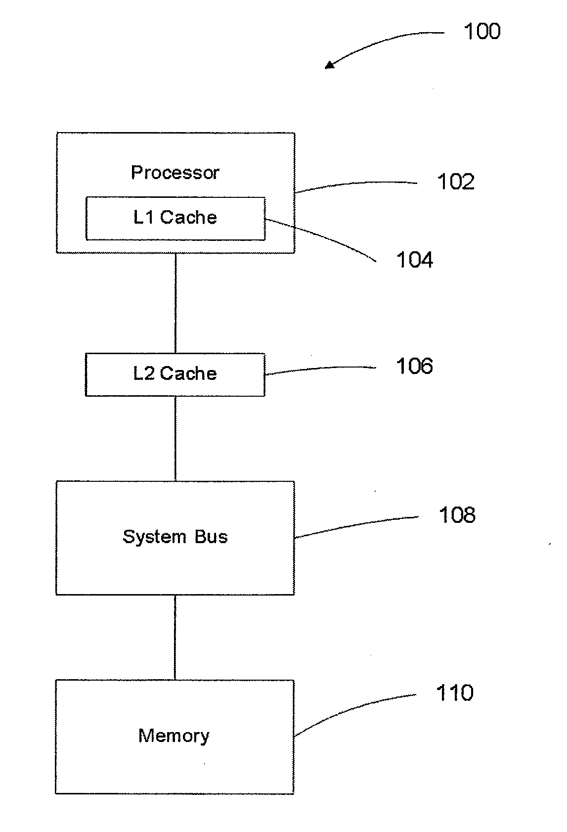
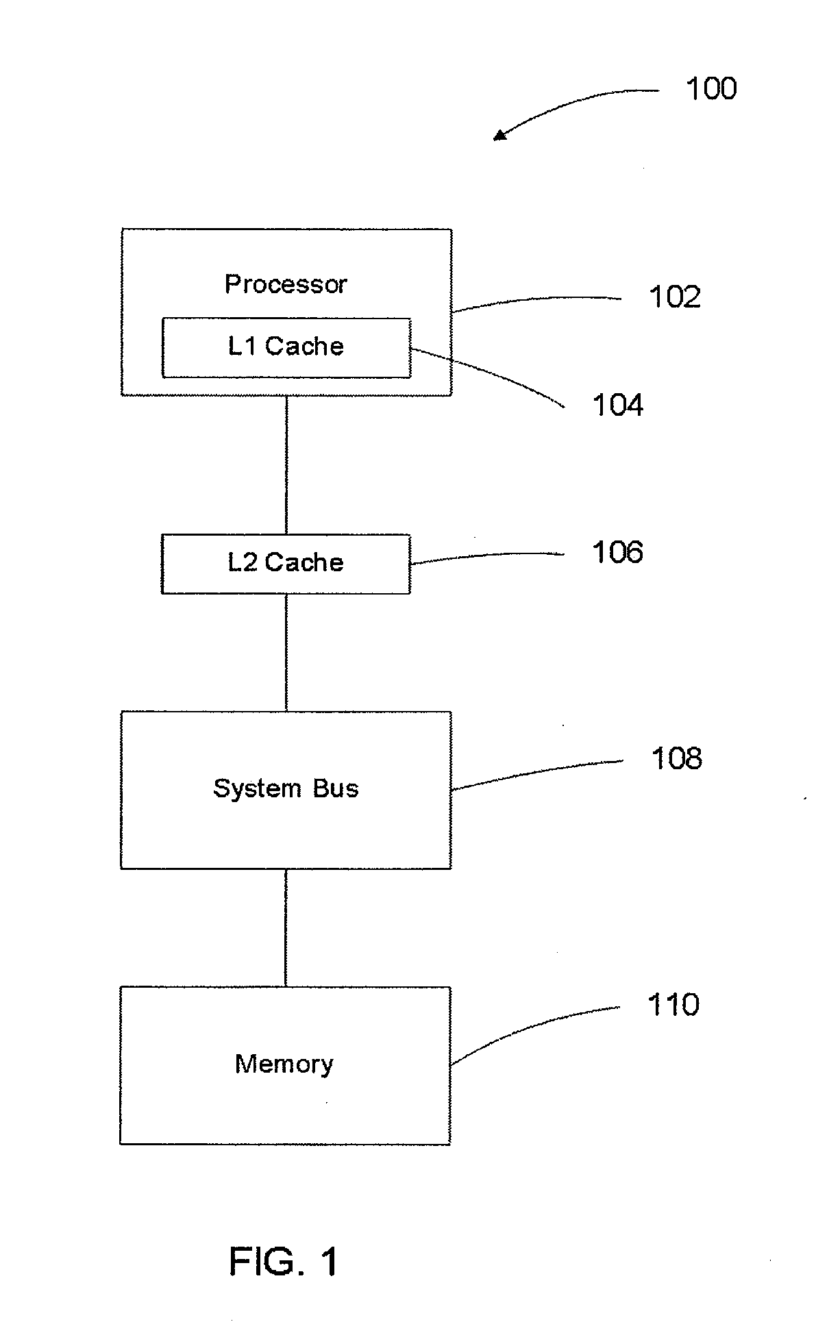
[0035]FIG. 1 shows one example of a computing system 100 suited for use with embodiments of the present invention. A processor 102 executes the instructions of a computer program. The effect of the computer program is to manipulate a hash table stored in the memory 110. A system bus 108 provides the physical means by which data is transferred between the processor 102 and the memory 110.

[0036]To improve the performance of the computing system 100, an L1 cache 104 and L2 cache 106 are typically placed in the data path. These caches 104, 106 improve performance by providing a limited amount of higher performance memory to buffer access to the memory 110. The L1 cache 104 is usually integral to the construction of the processor 102 and consequently has high performance but is constrained to a small size. The L2 cache 106 is usually external to the packaging of the processor 102 and provides buffering that is intermediate in performance and capacity between that of the L1 cache 104 and ...


PUM


Abstract

Method and apparatus for building large memory-resident hash tables on general purpose processors. The hash table is broken into bands that are small enough to fit within the processor cache. A log is associated with each band and updates to the hash table are written to the appropriate memory-resident log rather than being directly applied to the hash table. When a log is sufficiently full, updates from the log are applied to the hash table insuring good cache reuse by virtue of false sharing of cache lines. Despite the increased overhead in writing and reading the logs, overall performance is improved due to improved cache line reuse.

Description

CROSS-REFERENCE TO RELATED APPLICATIONS[0001]This application claims the benefit of U.S. Provisional Patent Application No. 60 / 904,112, filed Feb. 27, 2007, the contents of which are incorporated herein by reference as if set forth in their entirety.FIELD OF THE INVENTION[0002]The present invention relates to methods and apparatus for organizing data and, more particularly, to methods and apparatus for improving the performance of hash table updates.BACKGROUND OF THE INVENTION[0003]Hash tables are data structures that are used in data processing applications where high performance data retrieval is critical. Data retrieval in a hash table generally consists of finding a value that is uniquely associated with a key. The data structures for storing these key-value pairs can take many forms, including trees and linear lists. There are also many functions suited to associating a value with a key. The defining characteristic of hash table lookup is that for the majority of accesses, a ke...

Claims


Application Information

Patent Timeline
04 Sep 2008
Publication
US20080215849A1
IPC
G06F12/00
CPC
G06F17/30949; G06F12/0802; G06F16/9014
Inventors
SCOTT, THOMAS