Excavation apparatus

a technology of excavating apparatus and kelly, which is applied in the direction of earth drilling, drilling machines and methods, mining structures, etc., can solve the problems of difficult replacement of kelly sections, difficult exchange of kelly sections, and increased difficulty in changing and/or replacing kelly sections, so as to increase torque and increase transmission output , the effect of decreasing the time required

Inactive Publication Date: 2008-09-11
HOWELL JR RICHARD L
View PDF36 Cites 34 Cited by
  • Summary
  • Abstract
  • Description
  • Claims
  • Application Information

AI Technical Summary

Benefits of technology

[0050]In one embodiment the torque converter is a one speed transmission that can increase the torque applied to the output shaft of the transmission by up to about three times that of the torque applied to the input shaft of the transmission.
[0051]In another embodiment the torque converter is a two speed transmission that when drilling or excavating can also increase the transmission output torque up to about three times that of the transmission input shaft torque. However, when the kelly sections are fully retracted the transmission is automatically shifted into direct drive thereby increasing the transmission output shaft speed or RPM so that it equals that of the transmission input shaft speed or RPM, and thereby decreasing the time required to discharge soil from the auger.

Problems solved by technology

The weight of the device, which does not have a power downcrowding mechanism, forces the auger into the ground.
The pulley systems and the derrick would make it difficult to interchange the kelly sections since free access to the top of the kelly sections is not possible in such a rig.
Since the top of the kelly assembly is closed changing and / or replacing the kelly sections is more difficult than if the top of the outer kelly section were open.
U.S. Pat. No. 4,938,296 does not disclose a telescopic shaft between the variable displacement motor and the two speed gear box and the planetary gear.
Travel of the transmission downhole may not be possible with this rig.

Method used


Image

  • Excavation apparatus
  • Excavation apparatus
  • Excavation apparatus

Examples


operational example

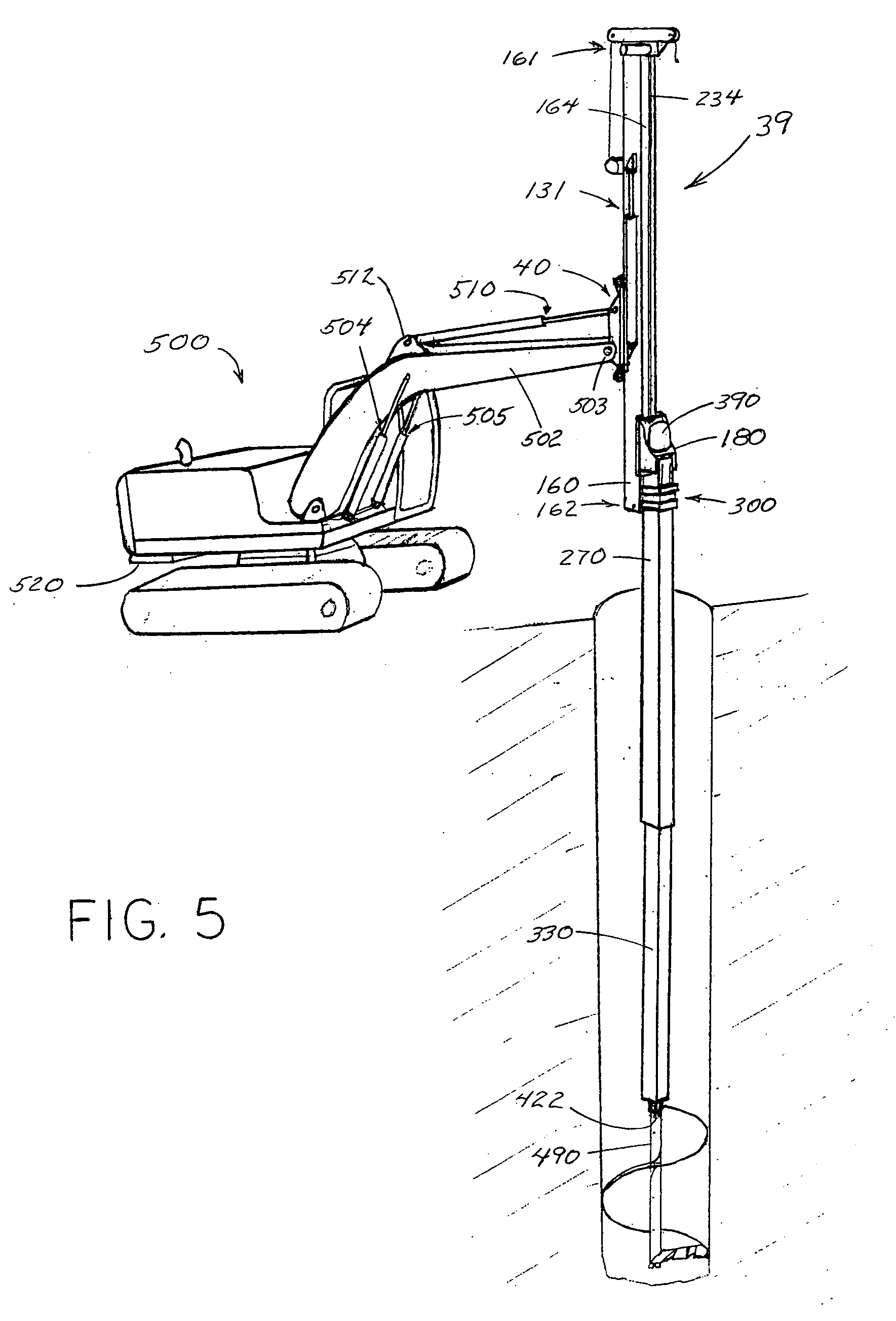
[0290]The excavation on a sloping grade for preparing a foundation site for the installation of a microwave relay cell tower.

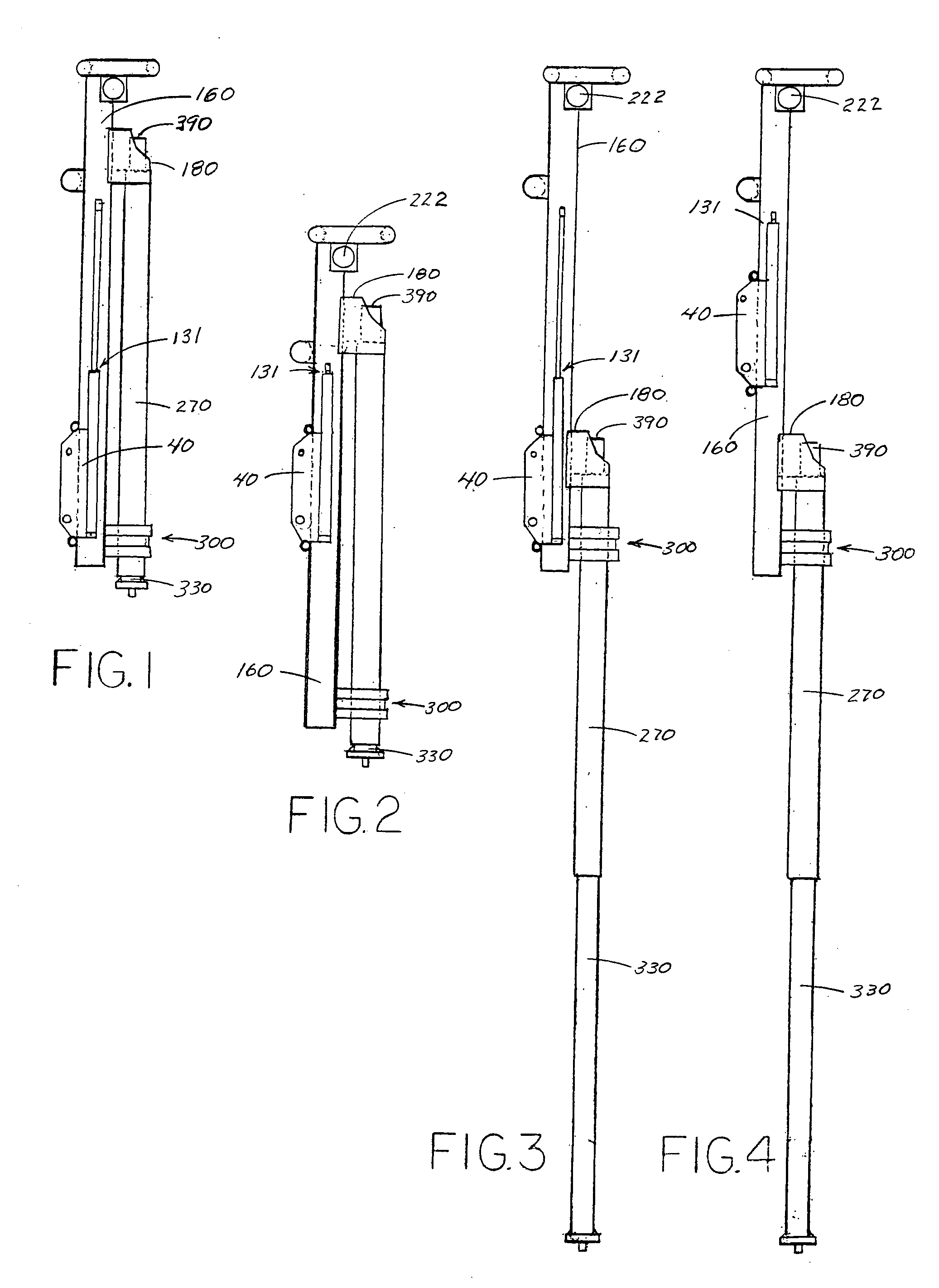
[0291]With the excavation apparatus mounted on a tractor at the site for excavation and auger attached to end 422 of shaft, the mast 160 and sled 180 are fully upcrowded. With boom connector 40 at a convenient height, the mast is positioned vertically over the site a small distance above the ground. The sled is downcrowded until the auger touches the ground. The auger is rotated in the excavation direction and the mast is then downcrowded to fill the auger with soil.

[0292]Rotation of the auger is stopped and the mast and sled are then fully upcrowded, thereby bringing the excavated soil above ground. The boom of the tractor is then swung over to a temporary soil accumulation site and the auger rotated in an unload direction, thereby unloading the soil.

[0293]The boom is then returned to the excavation site, the sled downcrowded to the bottom of the hole and aug...


PUM


Abstract

An excavation apparatus, for mounting on track type excavator, having a mast, a sled slidably mounted on the mast, a sled driving system supported by the mast for downcrowding and upcrowding the sled along the mast, and an extendable kelly section system that prevents slippage of the sled relative to the mast. The extendable kelly section system has a non-rotating outer kelly section attached to the sled, and a non-rotating inner kelly section that is extendable from and retractable into the outer kelly section. A bushing assembly maintains the outer kelly section slidable on the mast. The inner kelly section is automatically powered into and out of the outer kelly section a distance proportional to the distance that the sled is downcrowded or upcrowded along the mast while preventing slippage of the inner kelly section relative to the outer kelly section. A rotary motor, attached to the sled, rotates a telescopic shaft housed within the non-rotating kelly sections, which provides rotary power to an excavation tool. Alternatively, a transmission is secured to the lower end of the inner kelly section and the lower end of the telescopic shaft is connected to the input shaft of the transmission to increase the torque to the excavation tool. The transmission, which does not have an external source of transmission fluid, can be a one speed or two speed and can travel downhole. A boom connector and a mechanism for downcrowding and upcrowding the mast on the boom connector provides additional drilling depth capability. A side-to-side mechanism tilts the mast relative to the plane of the boom.

Description

CROSS-REFERENCE TO RELATED APPLICATIONS[0001]This application claims the benefit of U.S. Provisional Application Ser. No. 60 / 905,201, filed Mar. 6, 2007 and entitled “EXCAVATION APPARATUS.”BACKGROUND OF THE INVENTION[0002]Non-rotating kelly sections are shown in a drilling device in U.S. Pat. No. 1,971,922. The weight of the device, which does not have a power downcrowding mechanism, forces the auger into the ground.[0003]U.S. Pat. No. 3,426,857 shows a drilling device with a single kelly bar supported from the end of a boom of a track type vehicle. The single kelly bar slides through a housing of a rotatable guide which rotates the kelly bar. The rotatable guide is supported frame attached to the lower portion of the boom. No means of downcrowding is provided. Another rig with telescoping kelly sections is shown in U.S. Pat. No. 3,753,468. The outer kelly section slides axially within a guidance sleeve supported at its top end by the free end of the boom and at its bottom end by a ...

Claims


Application Information

Patent Timeline
Patent Type & Authority Applications(United States)
IPC IPC(8): E21B7/02
CPCE21B7/022E21B7/027E21B7/025E21B7/023
Inventor HOWELL, RICHARD L.
Owner HOWELL JR RICHARD L
Why Eureka
Try Eureka