Disc Brake and an Additional Brake Actuator Therefore

a brake actuator and disc brake technology, applied in the direction of actuators, mechanically actuated brakes, braking elements, etc., can solve the problem that no known design has been able to meet all requirements, and achieve the effect of simplifying and minimizing the design of the actuator

Inactive Publication Date: 2008-09-11
HALDEX BRAKE PROD AB
View PDF8 Cites 42 Cited by
  • Summary
  • Abstract
  • Description
  • Claims
  • Application Information

AI Technical Summary

Benefits of technology

[0027]The parking brake actuator according to the invention allows for an arc-shaped movement of the push rod from the service brake actuator, which further facilitates a combination with current designs of servi...

Problems solved by technology

However, no known design has b...

Method used


Image

  • Disc Brake and an Additional Brake Actuator Therefore
  • Disc Brake and an Additional Brake Actuator Therefore
  • Disc Brake and an Additional Brake Actuator Therefore

Examples


second embodiment

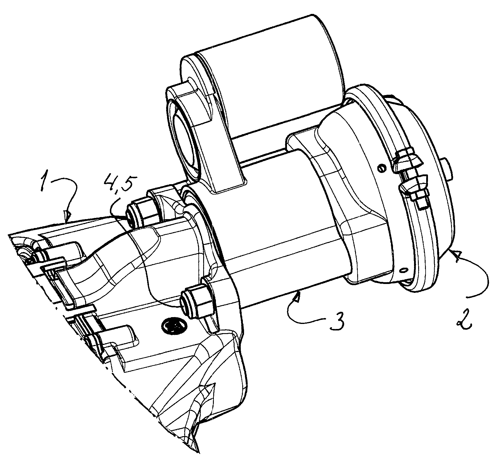
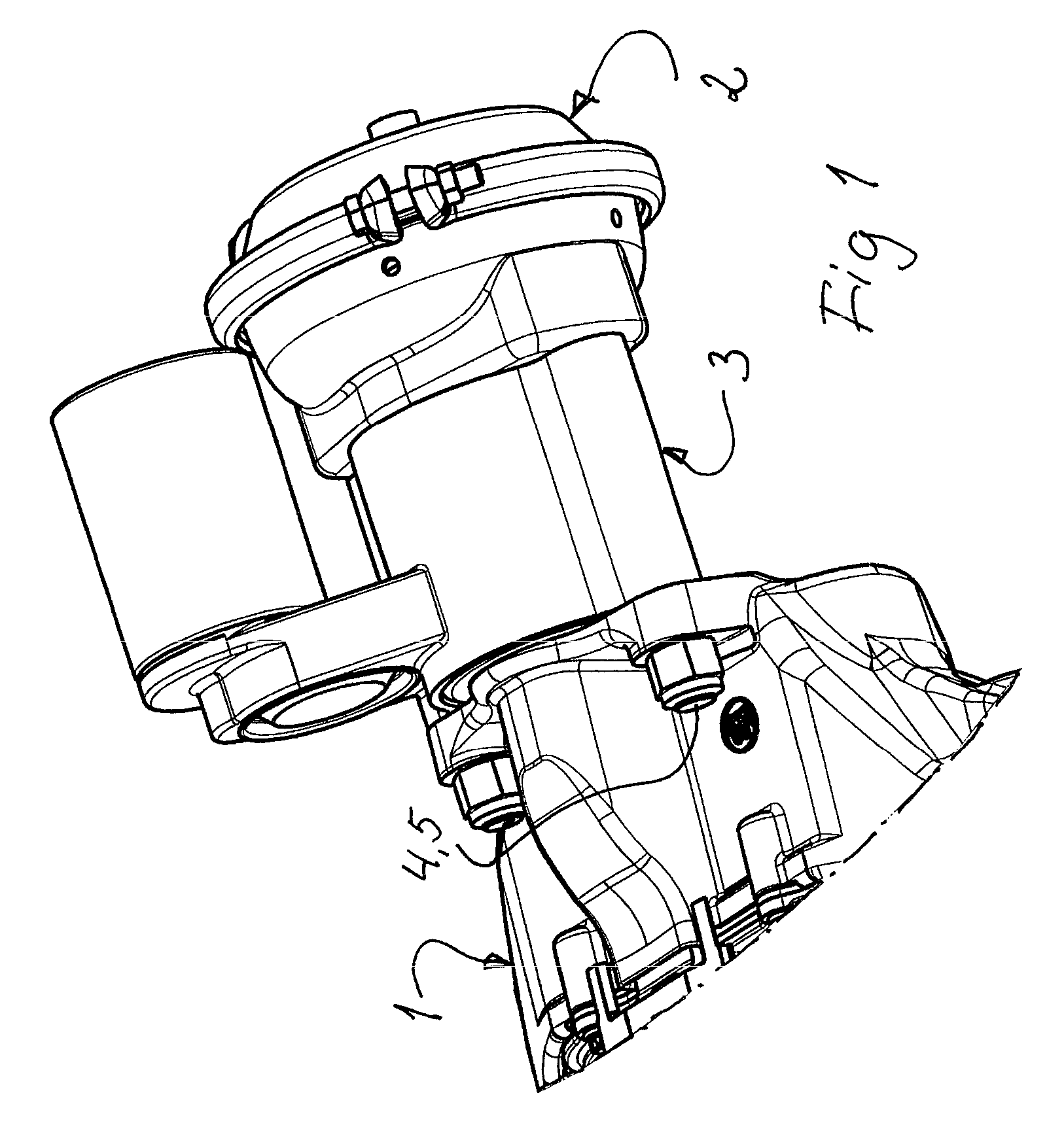
[0061]FIGS. 7 and 8 show a parking brake actuator with similar functional characteristics as the one shown in FIGS. 1-5 but with a more compact design. As the actuator can be made with a shorter axial length, its installation space can be reduced, which may be of great advantage in vehicles, where the available space often is extremely limited. The same numerals are used for the different parts as in FIGS. 1-5 but with the addition of an “A”.

[0062]The following parts may thus be recognized (certain journalings being omitted): the piston rod 6, the push rod 7A, the lever 8, the housing 10A, the drive sleeve 11A, the thrust bearing 15A, the external gear 16A, the electric motor 17A, the motor transmission 18A, 19A, the drive socket 20A, the rollers 21A, the flange 25A, the fingers 26A, and the return spring 27.

first embodiment

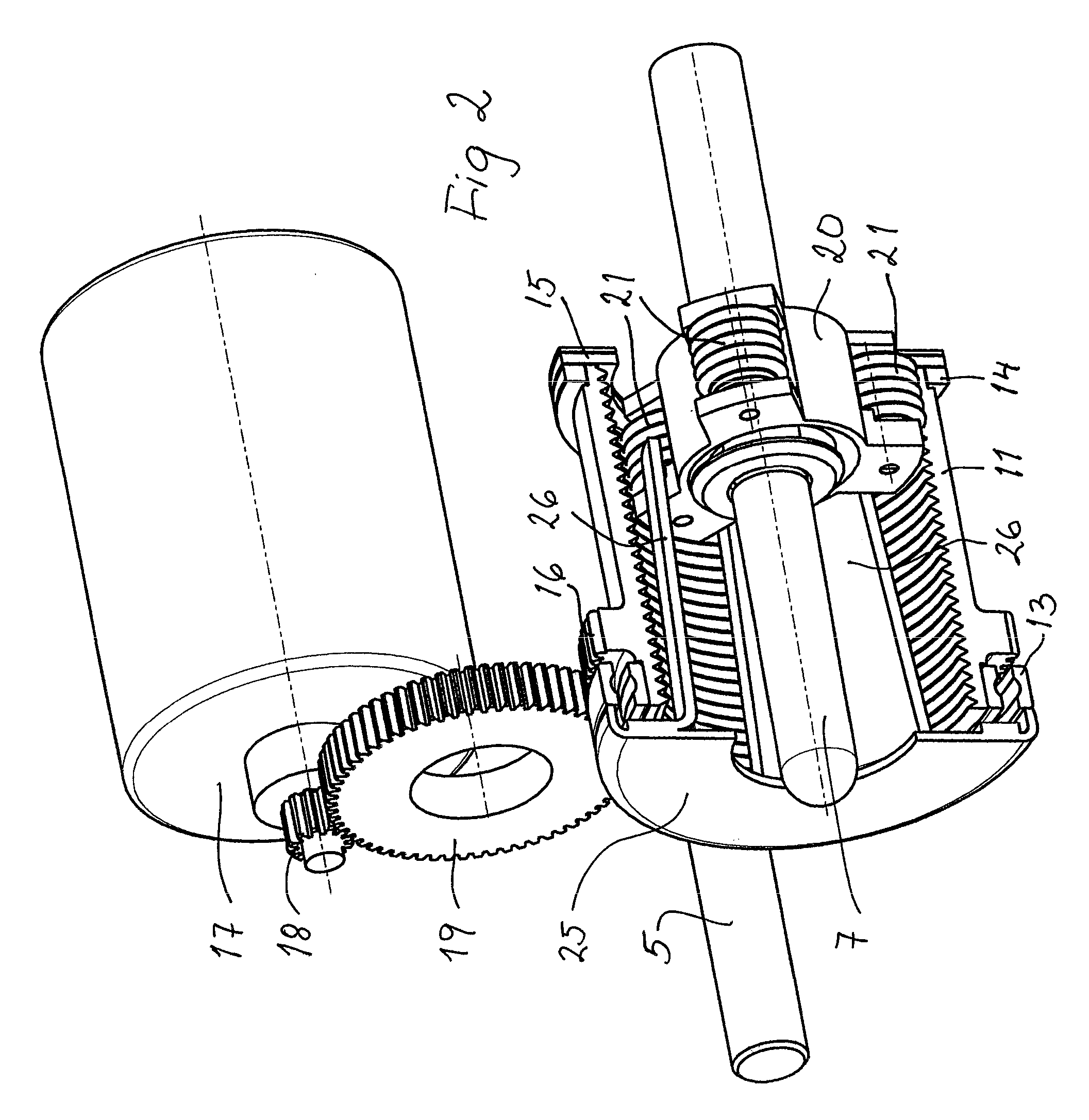
[0063]The main difference in relation to the first embodiment according to FIGS. 1-5 is that the push rod 7A here is provided with external threads, with which the rollers 21A of the drive socket 20A cooperate. In order to assure the intended function, the push rod 7A may be prevented from rotation for example by a non-rotatable connection to the amplification lever 8.

[0064]If only a park-lock function is required, the rollers 21A may be replaced with a conventional thread interaction, like in FIG. 6.

[0065]As has appeared above and in the Figures, there are means in the two embodiments of the invention, shown for example in FIGS. 3 and 7, respectively, for transforming the rotational movement of the drive sleeve 11 and 11A, respectively, into an axial movement of the push rod 7 and 7A, respectively, through the participation of the drive socket 20 and 20A, respectively.

[0066]In the first embodiment, for example shown in FIG. 3, there is an engagement between the inner thread 12 in t...


PUM


Abstract

A disc brake comprises a disc brake caliper, which includes a brake application mechanism with an input element, and a service brake actuator providing a brake application force to the input element via a push rod. An electromechanical brake actuator is arranged between the caliper and the service brake actuator and applies its force at will on the push rod.

Description

CROSS-REFERENCE TO RELATED APPLICATIONS[0001]The present application claims priority of Swedish patent application No. 0700525-9 filed on Mar. 5, 2007, the content of which is incorporated herein by reference.FIELD OF THE INVENTION[0002]The present invention relates to a disc brake, comprising a disc brake caliper, which includes a brake application mechanism with an input element, and a service brake actuator providing a brake application force to the input element via a push rod. It also relates to an additional brake actuator therefore.BACKGROUND OF THE INVENTION[0003]A disc brake of the above defined kind is today commonly used on trucks, buses and trailers, but other uses are also feasible. Primarily for obtaining a parking brake function or park-lock function for such a disc brake, an additional brake actuator, below often called a parking brake actuator for convenience, can be added. Many different requirements have to be fulfilled for such a parking brake actuator, and many ...

Claims


Application Information

Patent Timeline
IPC IPC(8): F16D65/34F16D55/224F16D65/28F16D65/18
CPCF16D65/18F16D2121/02F16D2121/24F16D2125/52F16D2125/32F16D2125/40F16D2125/48F16D2123/00F16D2055/0066
Inventor SEVERINSSON, LARSSTENSSON, GORAN
Owner HALDEX BRAKE PROD AB
Why Eureka
Try Eureka