Electric motor with static brake

Active Publication Date: 2008-09-11
ARVINMERITOR TECH
View PDF24 Cites 2 Cited by
  • Summary
  • Abstract
  • Description
  • Claims
  • Application Information

AI Technical Summary

Benefits of technology

[0008]The parking brake disk and the brake piston cooperate to provide a compact and effici

Problems solved by technology

One difficulty presented by the addition of an electric motor to a wheel drive unit is the incorporation of a static or parking brake fe

Method used


Image

  • Electric motor with static brake
  • Electric motor with static brake
  • Electric motor with static brake

Examples


Embodiment Construction

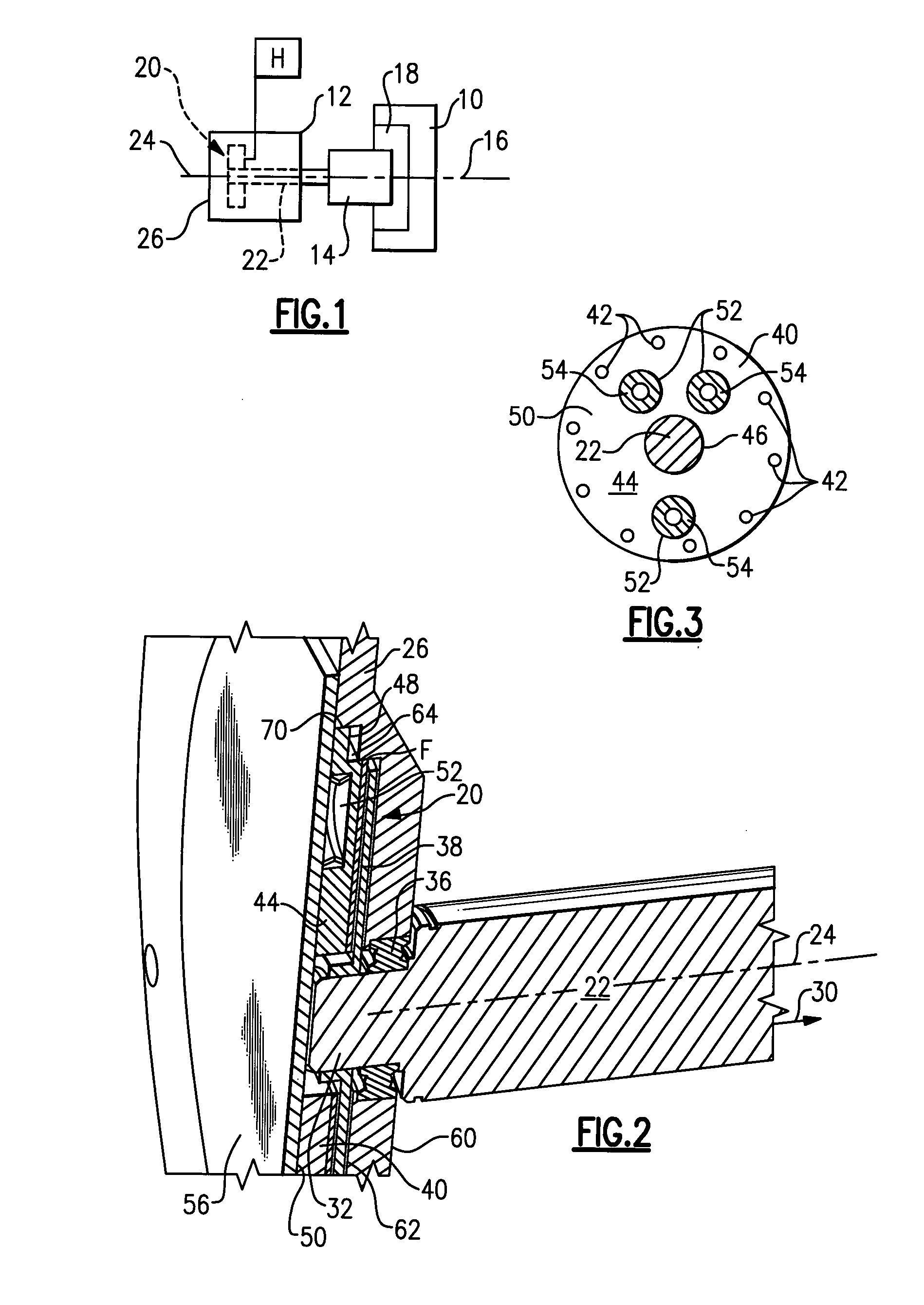
[0015]A vehicle wheel 10 is driven by an electric motor 12 as shown in FIG. 1. The electric motor 12 can be used to provide the sole driving input to the vehicle wheel 10 or can be used in a hybrid configuration to provide supplemental driving input to the vehicle wheel 10 as needed. In the example shown, the electric motor 12 drives a gear reduction 14, which in turn is coupled to drive the vehicle wheel 10; however, a gear reduction may not be required depending upon the vehicle application.

[0016]The vehicle wheel 10 rotates about a wheel axis 16 and includes a wheel brake 18 that applies a brake force to the wheel in response to operational braking requests that occur during vehicle operation. The wheel brake 18 can be any type of brake including a drum brake or disk brake, for example, and can be mechanically and / or electrically applied.

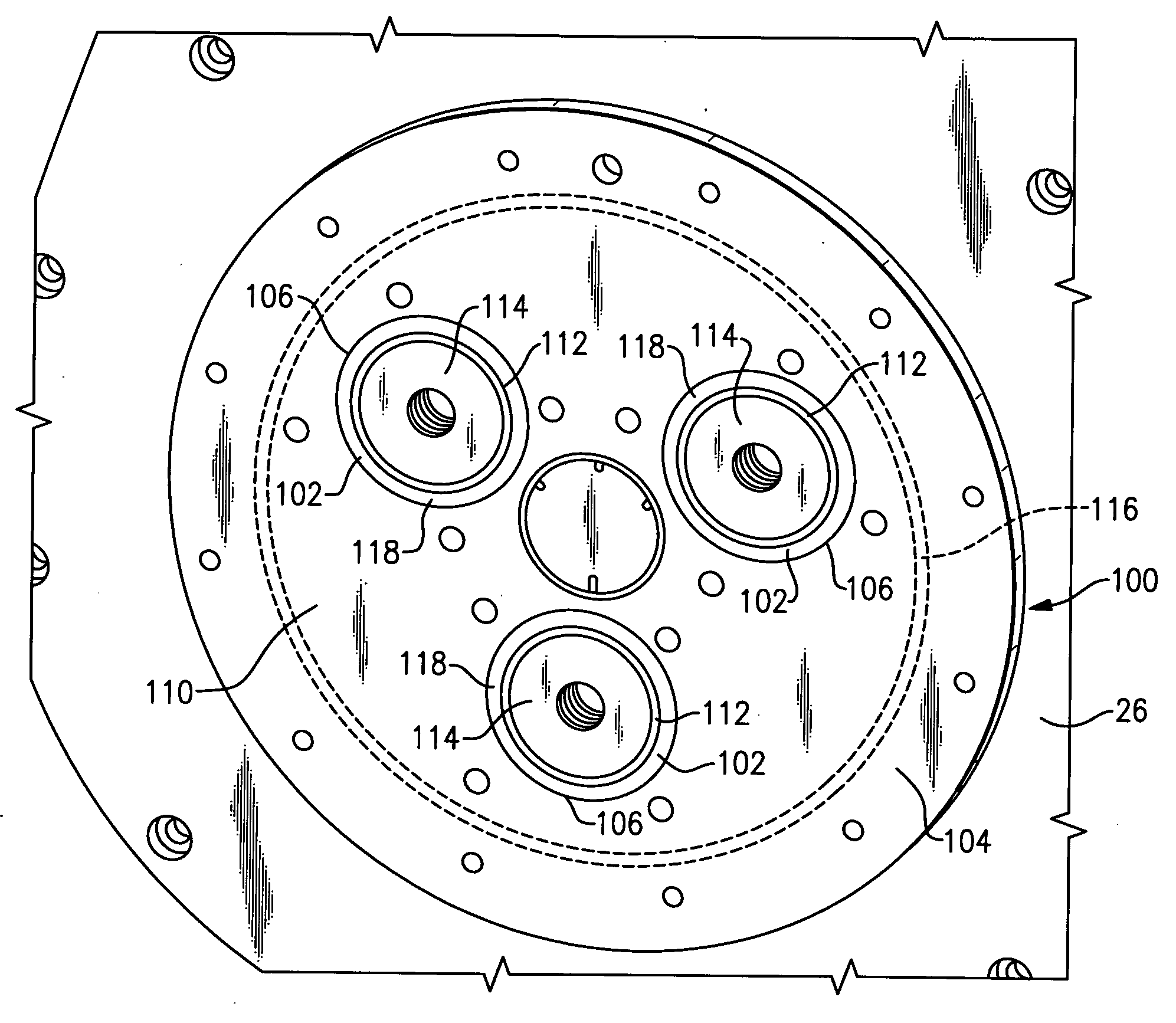
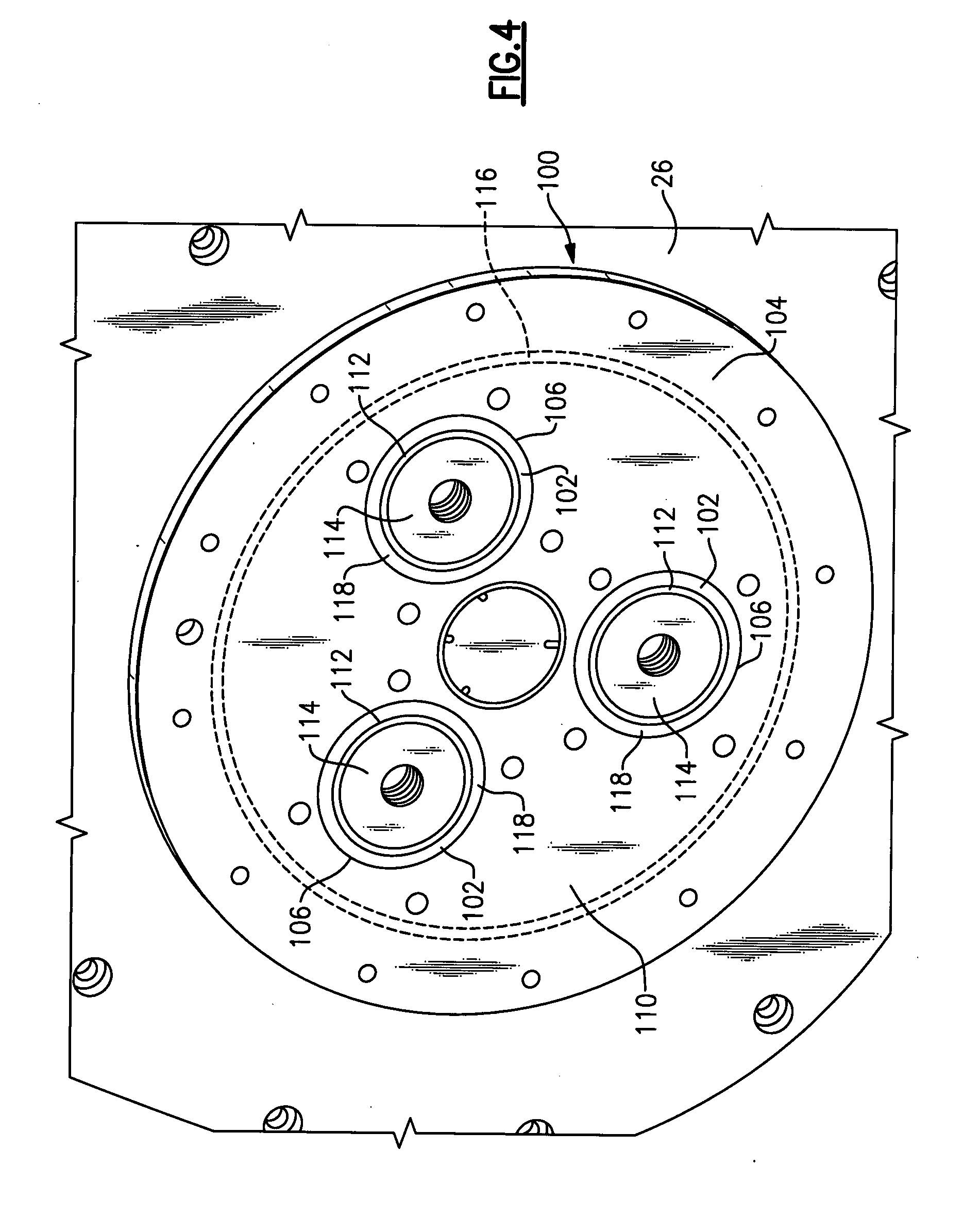
[0017]A static or parking brake 20 is associated with the electric motor 12 to provide a park brake feature at the vehicle wheel 10 that is inde...


PUM


Abstract

An electric motor for driving a vehicle wheel includes a parking brake that is selectively applied to provide a park brake condition. The parking brake is a clutch style brake and includes a sliding brake disk that is mounted for rotation with a motor shaft. A brake piston is used to move the sliding brake disk into engagement with a motor housing to achieve a park applied position. The parking brake is held in a release position by a hydraulic system that exerts a fluid pressure force against the brake piston. A resilient mechanism cooperates with the brake piston to apply the parking brake once the fluid pressure force is diminished.

Description

TECHNICAL FIELD[0001]The subject invention relates to a static brake that is incorporated into an electric motor for driving a vehicle wheel.BACKGROUND OF THE INVENTION[0002]Electric motors are often used to drive a wheel as opposed to using a traditional combustion engine powertrain. Electric motors can also be used as part of a hybrid configuration to provide supplemental driving power to the vehicle wheel. The use of electric motors offers improved fuel economy as a primary advantage.[0003]One difficulty presented by the addition of an electric motor to a wheel drive unit is the incorporation of a static or parking brake feature. In current motor configurations it is difficult to package an effective parking brake mechanism within the limited available space.[0004]Thus, there is a need for an electric motor and parking brake combination that can be effectively and efficiently packaged within available space at a wheel.SUMMARY OF THE INVENTION[0005]An electric motor for driving a ...

Claims


Application Information

Patent Timeline
IPC IPC(8): F16D55/18B60K1/00F16D55/08
CPCF16D65/186H02K7/102F16D2121/12
Inventor RITCHIE, ADAMSMITH, MARK C.COOPER, LON
Owner ARVINMERITOR TECH
Why Eureka
Try Eureka