
Clean input ups with fast rectifier control and improved battery life

a rectifier and input up technology, applied in the direction of dc conversion, power electronics conversion efficiency, emergency power supply arrangement, etc., can solve the problems of not being able to obtain the fast current control that is required, affecting the life of the battery, and acquiring sinusoidal currents at the price, so as to reduce the power drawn from the battery. , the effect of enhancing the response control performan

Inactive Publication Date: 2008-09-11
GENERAL ELECTRIC CO
View PDF8 Cites 26 Cited by
  • Summary
  • Abstract
  • Description
  • Claims
  • Application Information

AI Technical Summary

Benefits of technology

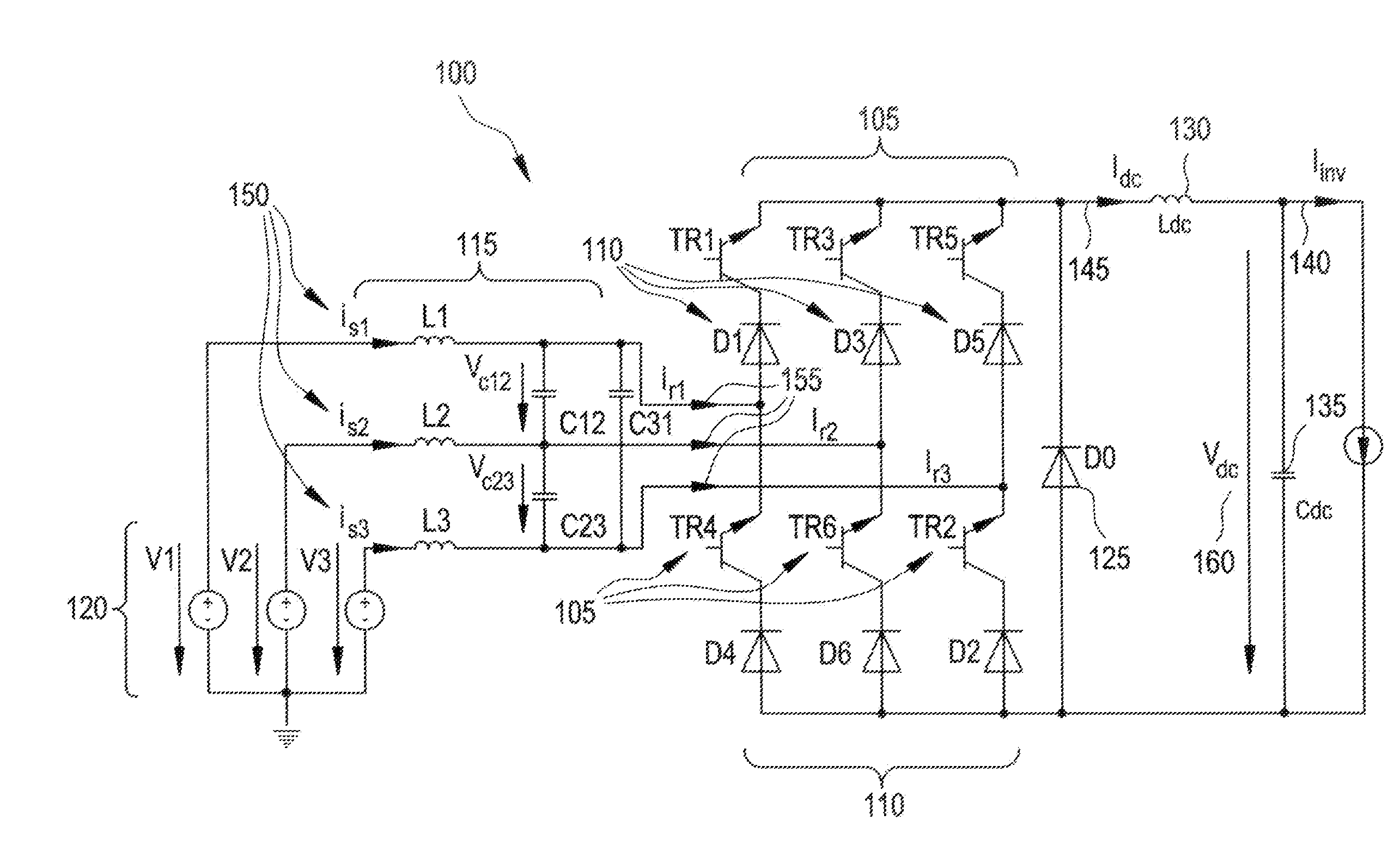
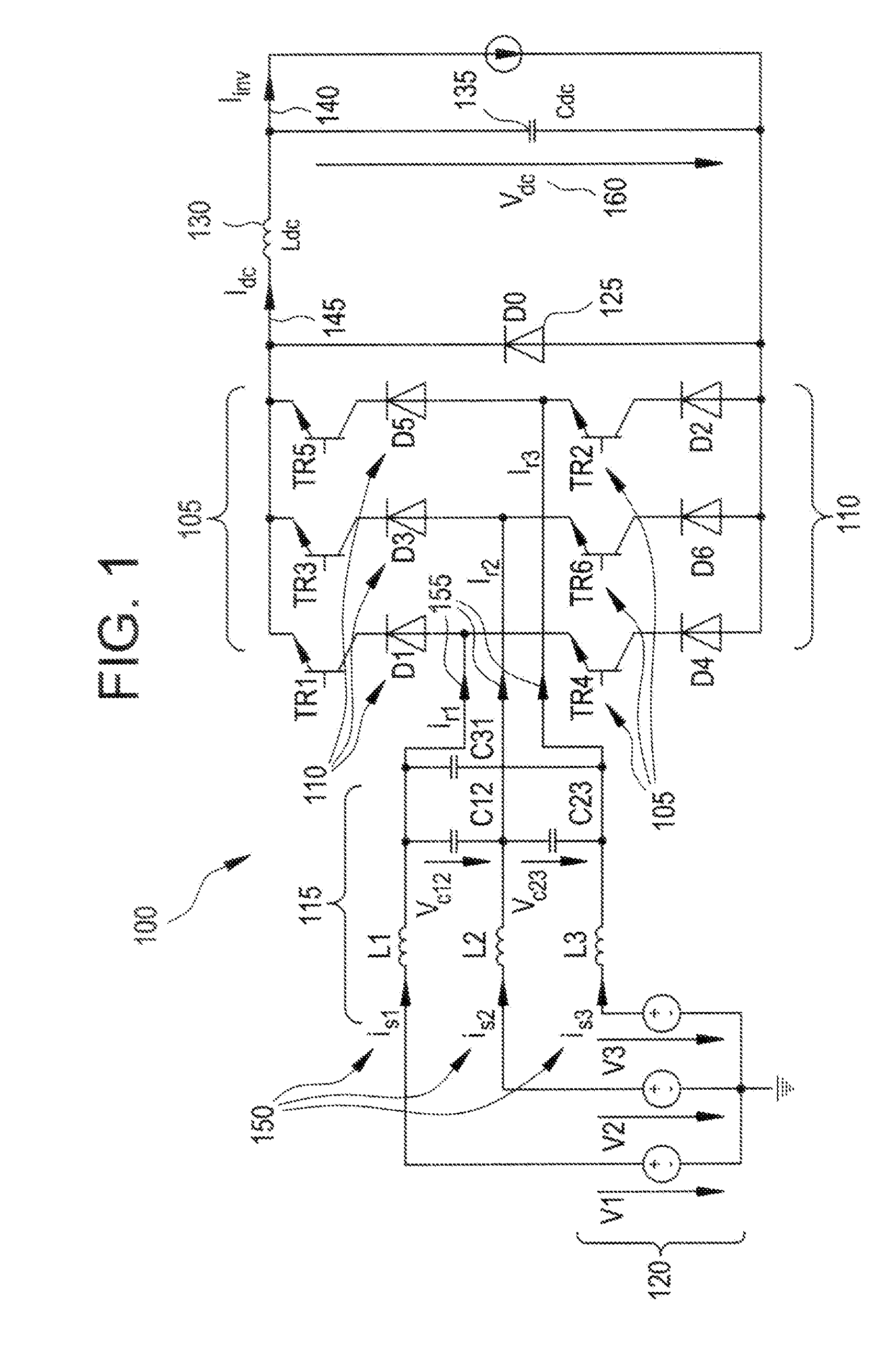
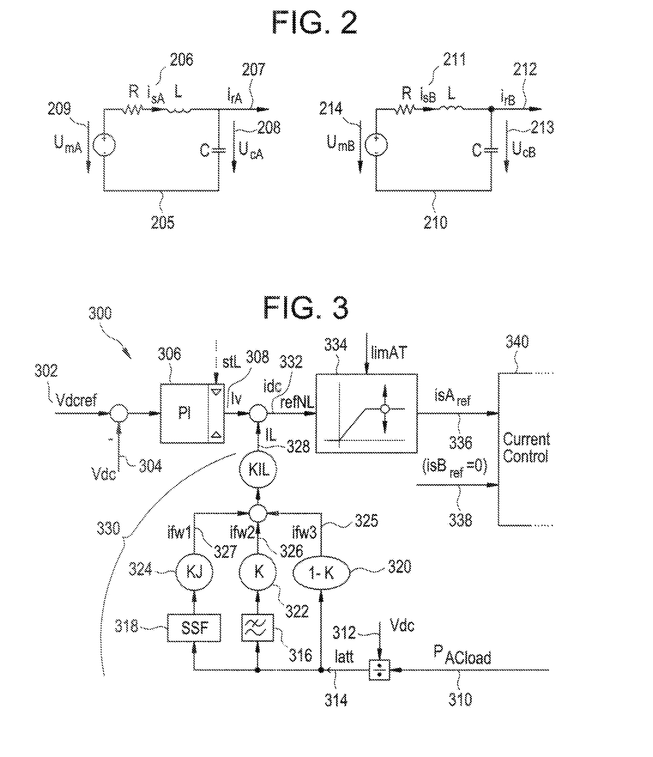
[0006]The present invention relates to the control of active rectifiers for uninterruptible power supplies. More specifically, aspects of the present invention comprise an active rectifier control system that is configured to enhance the response control performance for an uninterruptible power supply (UPS) system for servicing a load, the active rectifier control system providing rigid control of a direct current (dc) link voltage resulting from the combined linked outputs of a battery and the active rectifier, thus reducing the power drawn from the battery. The control system comprises a feed-forward voltage controller, the feed-forward voltage controller comprising a proportional-integral (PI) controller component, the PI controller component being configured to determine a voltage error reference current value in response to a dc voltage reference and a dc voltage input values, and a feed-forward current determining component, the feed-forward current determining component being configured to determine a feed-forward current value in response to an active current input value.
[0008]Further aspects of the present invention relate to an active rectifier control system method for enhancing the response control performance of an uninterruptible power supply (UPS) system for servicing a load, the method comprising determining an active power load value, dividing the active power load value by a dc voltage value in order to determine an active current input value, determining a feed-forward current value, and determining a voltage error reference current value. The method further comprises determining a dc reference input value from a summation of the voltage error reference current value and the feed-forward current value, providing the dc reference input value to a variable limitation component, wherein the variable limitation component is configured to utilize the dc reference input value to calculate a limited reference current value, and providing the limited reference current value to a current control component.

Problems solved by technology

Batteries that are implemented within, uninterruptible power supply (UPS) systems typically surfer from ripple currents and fast discharge pulses that can affect the life of a system-linked battery.
Normal rectifiers can only provide the mean value of this oscillating current, therefore, the ripple current must be drawn from the battery, thus affecting the life of the battery.
The first operating condition requires the drawing of constant active power from a utility, thus resulting in the acquisition of sinusoidal currents at the price of producing a high current ripple on the battery.
However, using these particular topologies, it was not possible to obtain the fast current control that is required to solve the above-mentioned problems.
However, additional control effort is required to take advantage of this fast current control in order to solve the mentioned problems, i.e. increase the battery life and obtain a very stiff dc link voltage control.

Method used


Image

  • Clean input ups with fast rectifier control and improved battery life
  • Clean input ups with fast rectifier control and improved battery life
  • Clean input ups with fast rectifier control and improved battery life

Examples


Embodiment Construction

[0019]One or more exemplary embodiments of the invention are described below in detail. The disclosed embodiments are intended to be illustrative only since numerous modifications and variations therein will be apparent to those of ordinary skill in the art.

[0020]The present invention relates to UPS systems, in particular with the control of active rectifiers for UPS systems. In operation, active rectifiers are used to realize clean input UPS systems that can draw sinusoidal currents from mains at a high power factor. Aspects of the present invention relate to a control system, wherein the control system is implemented to realize fast rectifier control operations that result in the improved life of a battery that is linked to the active rectifier of the UPS system. Within aspects of the present invention under unbalanced load conditions, it is possible to select the desired behavior between the two possible extreme conditions—that is the implementation of a clean power input that re...


PUM


Abstract

The present invention relates to the control of active rectifiers for UPS systems. Aspects of the present invention relate to a control algorithm that is implemented to realize a fast rectifier control operation that results in the improved life of a battery that is linked to the active rectifier of the UPS system. Within aspects of the present invention under unbalanced load conditions, it is possible to select (he desired behavior between the two possible extreme conditions, i.e. implement a clean power input that results in the reduced life of the battery or implement a non-clean power input resulting in the improved life of the battery. Additionally, the present invention utilizes fast rectifier control and specific feed-forward action to make it possible to obtain the very rigid control of a dc link voltage, even under extreme step load variations.

Description

BACKGROUND OF THE INVENTION[0001]1. Field of the Invention[0002]This invention relates to uninterruptible power supplies, and particularly to the control of active rectifiers for uninterruptible power supplies.[0003]2. Description of Background[0004]Batteries that are implemented within, uninterruptible power supply (UPS) systems typically surfer from ripple currents and fast discharge pulses that can affect the life of a system-linked battery. Under unbalanced load conditions, an output inverter draws at twice the mains frequency from a direct current (dc) Sink and an oscillating current that is produced by a rectifier and the battery. Normal rectifiers can only provide the mean value of this oscillating current, therefore, the ripple current must be drawn from the battery, thus affecting the life of the battery. In the event that a UPS load is unbalanced then, the associated active power is not constant. In this instance there is the possibility for two extreme operating condition...

Claims


Application Information

Patent Timeline
IPC IPC(8): H02M7/06
CPCH02J9/062H02M1/15H02M1/4208H02M1/4233Y02B70/1408H02M7/2173H02M7/219Y02B70/126H02M7/217Y02B70/10
Inventor COLOMBI, SILVIOBALBLANO, CLAUDIO
Owner GENERAL ELECTRIC CO
Learn More