Fast-Scanning SPM Scanner and Method of Operating Same

a scanner and fast scanning technology, applied in the field of scanning probe microscopes, can solve the problems of inability to achieve fast scanning speed, compromise signal-to-noise ratio and resulting image quality, and the practicable limit of afm scan speed, etc., to achieve the effect of high resonant frequency, fast acquisition of precise imaging data, and increased focus rang

Active Publication Date: 2008-09-18
BRUKER NANO INC
View PDF24 Cites 68 Cited by
  • Summary
  • Abstract
  • Description
  • Claims
  • Application Information

AI Technical Summary

Benefits of technology

[0016]In accordance with a first aspect of the invention, a SPM with an integrated optical microscope is provided having a scan had that can acquire precise imaging data very rapidly. An objective is provided in the scan head to focus sensing and illumination light on the probe of the SPM. The SPM has a relatively stiff, relatively light-weight scanner having a high fundamental resonant frequency. The objective preferably is vertically movable within the scan head to increase the focus range for a laser or other sensing light source, permitting the use of a relatively high cantilever with a commensurately high resonant frequency. The movable objective also permits illumination light to be focused on distinctly spaced objects, such as the probe and a sample surface located well beneath the probe. The objective is preferably also a “tracking objective” that moves with the scanner in the x-y plane to allow a sensing light beam's focused spot to remain focused on the probe during scanning. Optics are also preferably provided to permit panning of both the illumination beam of an integrated optical microscope and the sensing light beam as a unit. This panning permits the alignment or targeting of the focused sensing light beam on the cantilever under direct or indirect visual inspection of the focused illumination beam. This panning permits the use of an even smaller cantilever with a commensurately smaller resonant frequency.

Problems solved by technology

As with most measuring devices, AFMs often require a trade off between resolution and acquisition speed.
The practical limit of AFM scan speed is a result of the maximum speed at which the AFM can be scanned while maintaining a tracking force that is low enough not to damage or cause minimal damage to the tip and / or sample.
On the other hand, SPMs that can acquire data rapidly can also suffer unacceptable tradeoffs.
The Video AFM operates at video rates but with significant compromises to signal-to-noise ratio and resulting image quality.
The Infinitesima system also operates in contact mode with force feedback that is not fast enough to respond to variations in sample corrugation within a scan line.
As a result, only very small (on the order of a few mm in size) samples or cantilever substrates can be mounted to the tuning fork without degrading the performance.
High resolution optical imaging is therefore difficult to implement in combination with traditional AFM detectors because there is insufficient space between the bottom of the objective and the probe to accommodate the geometry for the incoming and outgoing detection beams.
Because of the weight of the optical microscope, it is difficult to incorporate the optics of an optical microscope into the scanner of the AFM without unacceptably reducing the instrument's scan rate.
Its objective is fixed relative to the probe, and it lacks any mechanism for dynamically focusing the laser beam onto the probe.
Another drawback of conventional optical microscope equipped AFMs is that the optical microscope is provided only to allow the user to inspect the sample.
Hence, even if the system were provided for focusing the light spot on the cantilever, no mechanism would be available to provide the user with optical feedback during a focusing process.

Method used


Image

  • Fast-Scanning SPM Scanner and Method of Operating Same
  • Fast-Scanning SPM Scanner and Method of Operating Same
  • Fast-Scanning SPM Scanner and Method of Operating Same

Examples


Embodiment Construction

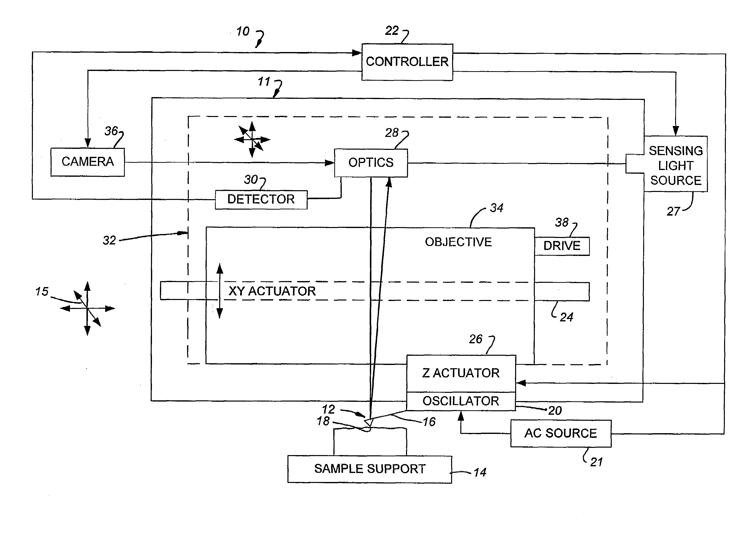
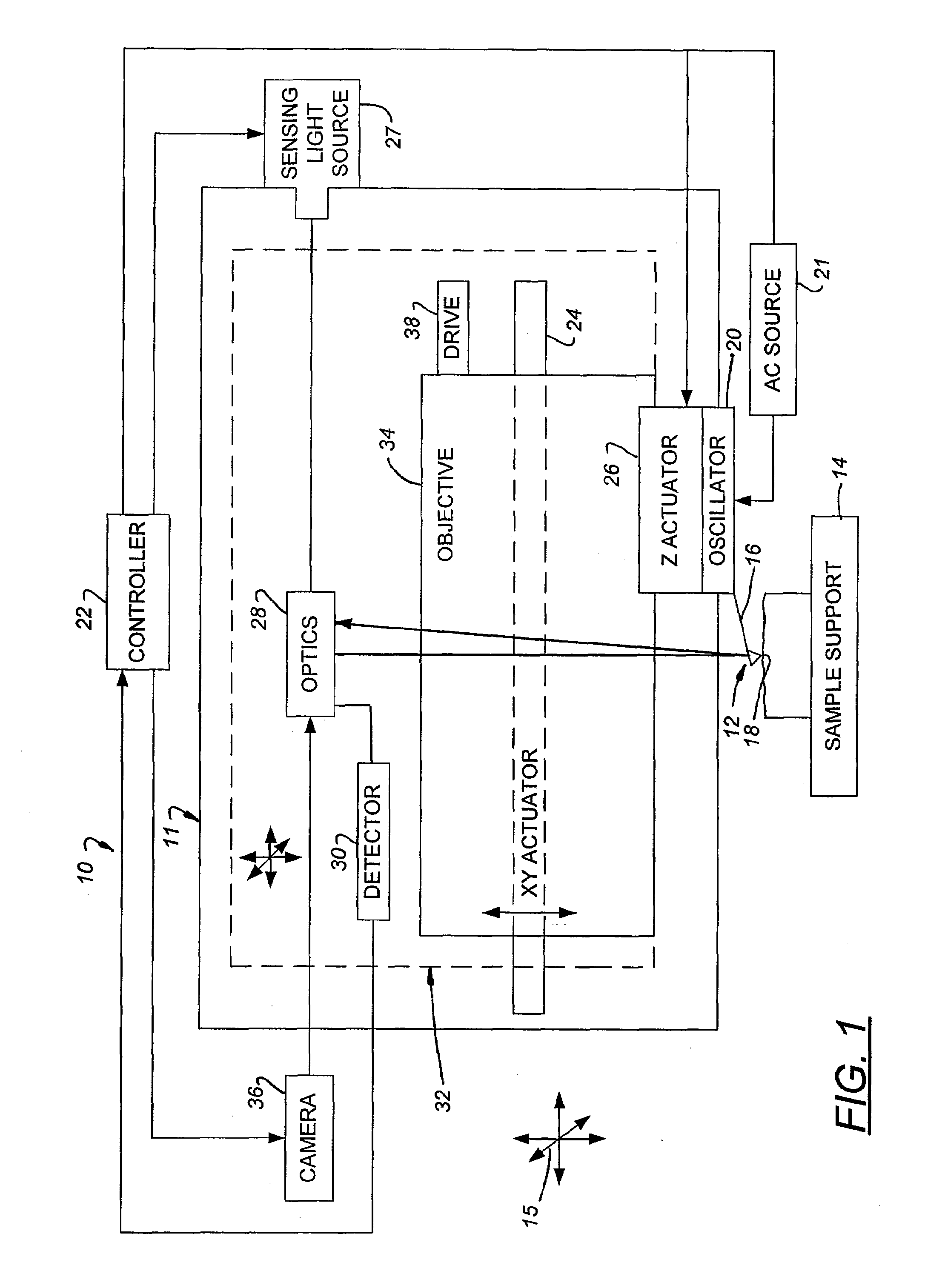
[0038]As discussed in the “Summary” section above, the invention relates to a fast-acting scan head for a scanning probe microscope (SPM) such as an atomic force microscope (AFM). The scan head includes a probe, an actuator for the probe, and an optical objective that collectively form a scanner that moves as a unit for scanning. They are also arranged to permit the sample to be inspected at engagement using an illumination beam, and to place the focal point of the sensing light beam on the cantilever of the probe.

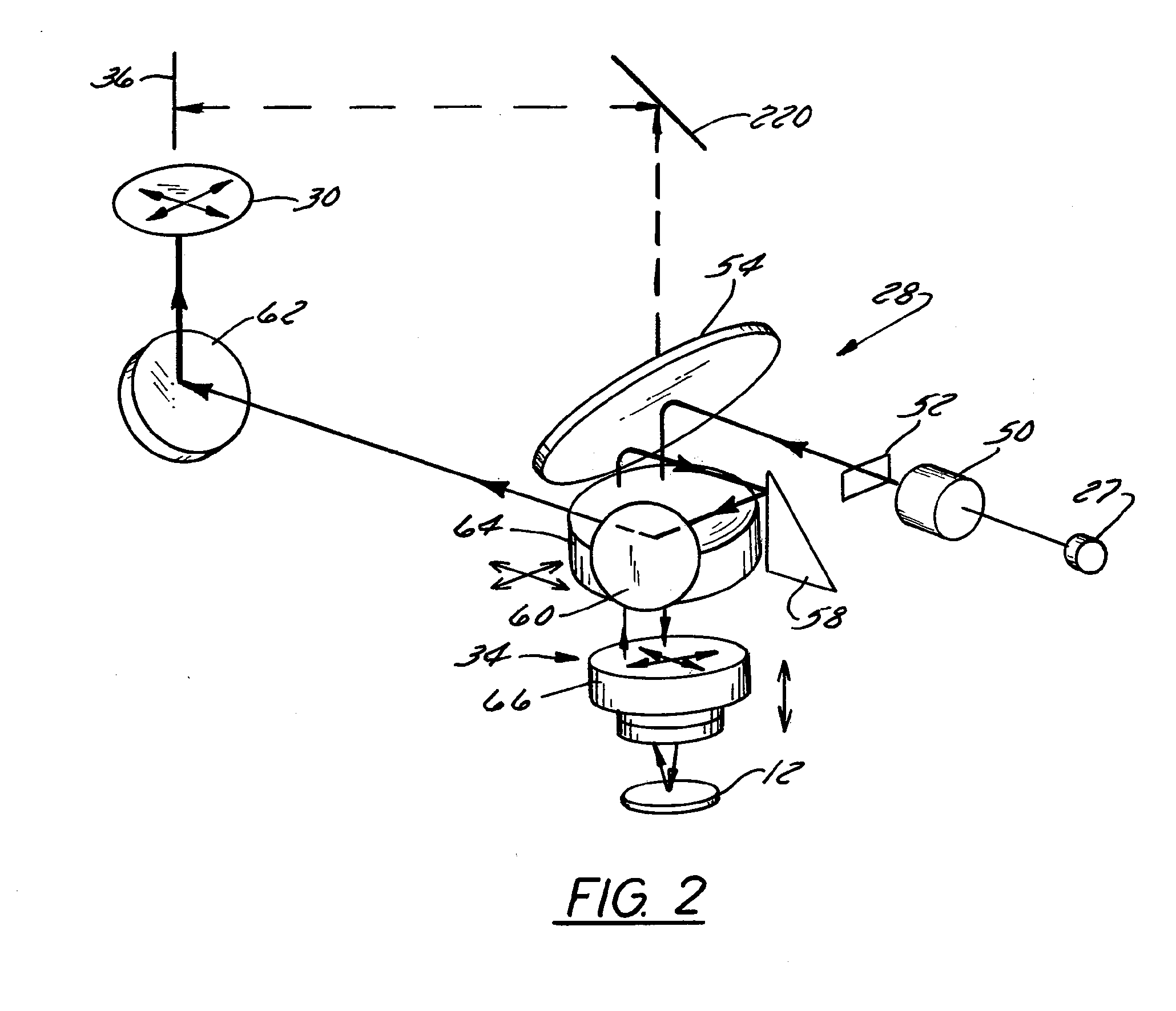
[0039]The objective may also be movable in the z direction to increase the range of focus of the objective. It also preferably comprises a targeting objective that moves with the scanner so as to remain focused on the cantilever during scanning. An AFM will now be disclosed having a scan head constructed in accordance with a preferred embodiment of the invention, it being understood that the scan head as disclosed can be used with a variety of other AFMs, other SPMs, and e...


PUM


Abstract

A high-bandwidth SPM tip scanner is provided that additionally includes an objective that is vertically movable within the scan head to increase the depth of focus for the sensing light beam. Movable optics also are preferably provided to permit targeting of the sensing light beam on the SPM's probe and to permit the sensing light beam to track the probe during scanning. The targeting and tracking permit the impingement of a small sensing light beam spot on the probe under direct visual inspection of focused illumination beam of an optical microscope integrated into the SPM and, as a result, permits the use of a relatively small cantilever with a commensurately small resonant frequency. A high-bandwidth tip scanner constructed in this fashion has a fundamental resonant frequency greater than greater than 500 Hz and a sensing light beam spot minor diameter of less than 10 μm. Images can be scanned on large samples having a largest dimension exceeding 7 mm with a resolution of less than 1 Angstrom and while scanning at rates exceeding 30 Hz.

Description

BACKGROUND OF THE INVENTION[0001]1. Field of the Invention[0002]The present invention is directed to scanning probe microscopes (SPMs), and, more particularly, relates to a scanner for a SPM that can acquire high-quality images at high acquisition rates and to a method of operating such a scanner.[0003]2. Description of Related Art[0004]Scanning probe microscopes (SPMs), such as the atomic force microscope (AFM), are devices which typically use a tip and low forces to characterize the surface of a sample down to atomic dimensions. Generally, SPMs include a probe having a tip that is introduced to a surface of a sample to detect changes in the characteristics of a sample. By providing relative scanning movement between the tip and the sample, surface characteristic data can be acquired over a particular region of the sample and a corresponding map of the sample can be generated.[0005]The atomic force microscope (AFM) is a very popular type of SPM. The probe of the typical AFM include...

Claims


Application Information

Patent Timeline
Patent Type & Authority Applications(United States)
IPC IPC(8): G01B5/28G01Q10/02G01Q20/02G01Q30/02
CPCB82Y35/00G01Q30/025G01Q20/02G01Q10/02G01Q10/00G01Q20/00
Inventor PHAN, NGHICUSWORTH, CRAIGPRATER, CRAIG
Owner BRUKER NANO INC
Why Eureka
Try Eureka