

Potentiostat circuit
a potentiostat and circuit technology, applied in the field of measuring apparatus, can solve the problems of increasing the measurement time, requiring expensive measures to keep samples in a stable condition, and samples may degrade or disintegra
- Summary
- Abstract
- Description
- Claims
- Application Information
AI Technical Summary
Benefits of technology
Problems solved by technology
Method used
Image

Examples
first embodiment
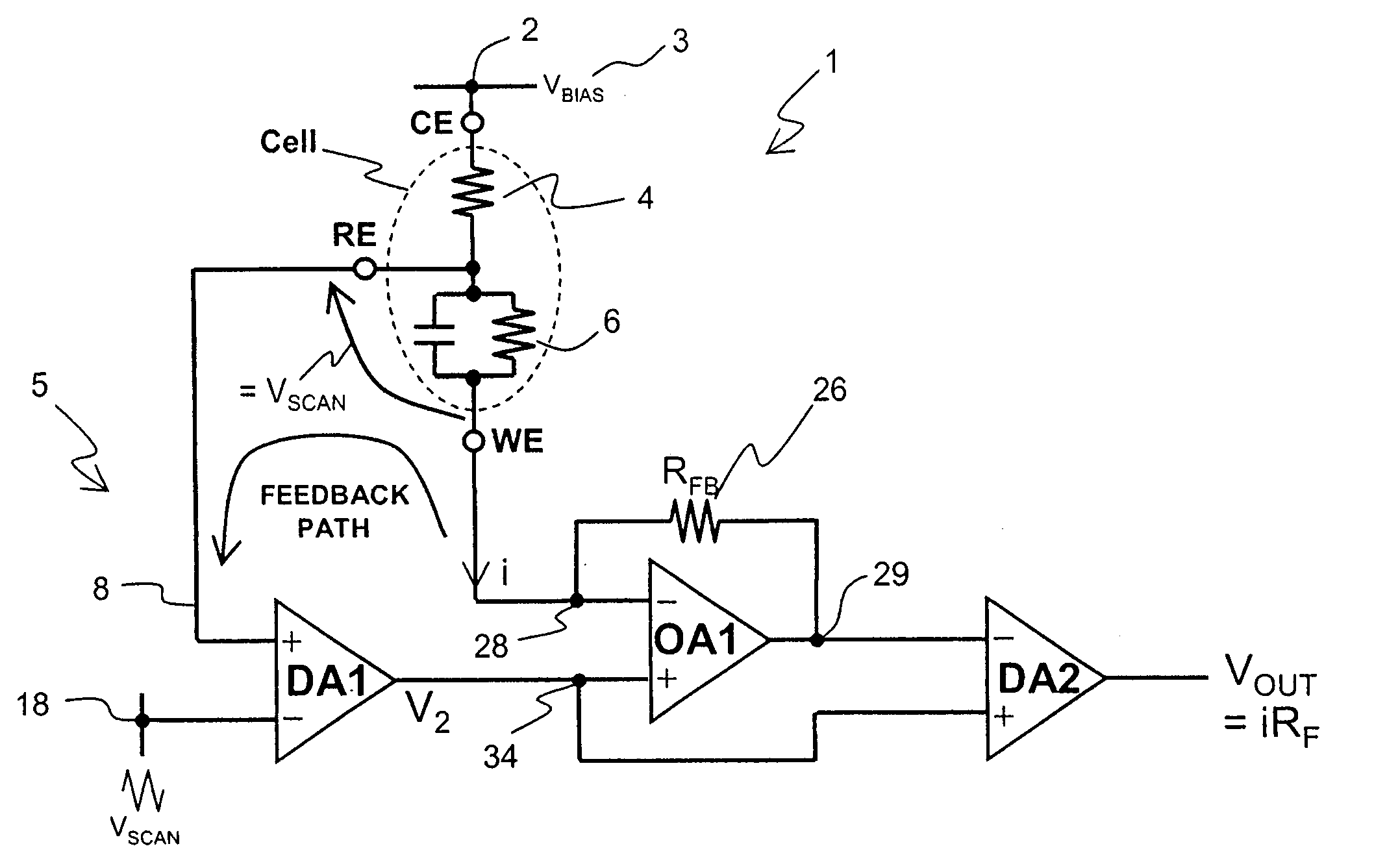
[0032]Referring to FIG. 5a, the present invention comprises a biosensor circuit 1 consisting of a three terminal electrochemical cell, differential amplifiers and a current-to-voltage converter, with a feedback voltage signal path formed between the working electrode WE and the reference electrode RE. The three terminal electrochemical cell is formed using the counter electrode CE, the reference electrode RE and the working electrode WE. The counter electrode CE is connected to a first voltage supply rail 2 connected to a bias voltage VBIAS 3. A first resistor 4 is connected between the counter electrode CE and a reference electrode RE and represents an electrolyte comprising at least one target biological molecule. In a similar manner to that illustrated in FIG. 2, the reference electrode RE is disposed upon an insulator (not shown in FIG. 5) in close proximity to a working electrode WE, which is disposed upon a bioreceptive layer modeled in FIG. 5a by a parallel resistor and capac...
second embodiment
[0037]Referring to FIG. 6, the present invention comprises of a biosensor circuit 1, consisting of a three terminal electrochemical cell, differential amplifiers and a current-to-voltage converter, with a feedback voltage signal path formed between the working electrode WE and the reference electrode RE. The three terminal electrochemical cell is formed using the counter electrode CE, the reference electrode RE and the working electrode WE. The counter electrode CE is connected to the first voltage supply rail 2 connected to a bias voltage VBIAS 3 equal to the system ground. A first resistor 4 is connected between the counter electrode CE and a reference electrode RE and represents an electrolyte comprising at least one target biological molecule. In a similar manner to that illustrated in FIG. 2, the reference electrode RE is disposed upon an insulator (not shown in FIG. 6) in close proximity to a working electrode WE, which is disposed upon a bioreceptive layer represented in FIG....
third embodiment
[0046]Referring to FIG. 8b, a multi-channel biosensor circuit l is arranged for simultaneous readout according to the present invention and comprises an array of counter electrodes CE, reference electrodes RE, working electrodes WE, electrolytes, bioreceptor layers and potentiostat circuits 5.
[0047]The counter electrodes CE are connected to a first voltage supply rail 2 connected to ground or a DC voltage source 3. Each counter electrode CE is connected to a first terminal of a first resistor 4 having a second terminal connected to the reference electrode RE. The first resistor 4 represents the electrolyte comprising at least one target biological molecule. In a similar manner to that illustrated in FIG. 3, the reference electrode RE is disposed upon an insulator 30 (not shown in FIG. 8b) in close proximity to a working electrode WE, which is disposed adjacent a bioreceptor layer represented in FIG. 8b by a parallel resistor and capacitor arrangement 6.
[0048]Each reference electrode...
PUM
| Property | Measurement | Unit |
|---|---|---|
| Electric potential / voltage | aaaaa | aaaaa |
Abstract
Description
Claims
Application Information