Homeostatic flying hovercraft

a hovercraft and homeostatic technology, applied in aircraft navigation control, process and machine control, instruments, etc., can solve the problems of difficulty in controlling and maneuvering, and difficulty in controlling and controlling this craft. to achieve the effect of easy control

Inactive Publication Date: 2008-09-18
QFO LABS
View PDF59 Cites 27 Cited by
  • Summary
  • Abstract
  • Description
  • Claims
  • Application Information

AI Technical Summary

Benefits of technology

[0026]The present invention is a homeostatic flying hovercraft that preferably utilizes at least two pairs of counter-rotating ducted fans to generate lift like a hovercraft and utilizes a homeostatic hover control system to create a flying craft that is easily controlled. The homeostatic hover control system provides true homeostasis of the craft with a true fly-by-wire flight control and control-by-wire system control.
[0027]In one embodiment, the flying hovercraft is a flying saucer shaped over-powered skirtless hovercraft capable of up / down, lateral and yaw, pitch and roll flight maneuvers by mimicking the position of the craft to the position of a remote controller. Preferably, control is fluidly intuitive by seamlessly utilizing a series of pre-established operational orientations associated with each of the positions of the craft that result in balanced and controlled flight positions. The homeostatic hover control system removes the need for the pilot to be concerned with moment-to-moment balance / stabilization and control of the craft and focus instead only on the intended motion in which the craft is to be directed.
[0028]Instead of trying to use the rotation of the craft or the spinning of rotor blades to provide aerodynamic lift, the preferred embodiment of the homeostatic flying saucer uses four battery-powered ducted fans housed completely inside the craft to produce four controlled cones of thrust beneath the craft. A novel control system balances the four cones of thrust to keep the craft stable and to cause the craft to move in a desired direction. The fan blades are specially designed to make the most efficient use of the increased power provided by permanent magnet motors while also reducing fan noise both because the blades spin somewhat slower than conventional blades and because of the unique aerodynamic design features of the ducted fan blades.

Problems solved by technology

While numerous concepts relating to spinning, flying disc-shaped craft have been put forth in a variety of patents and publications, a practical embodiment of a self-powered flying saucer has yet to be developed.
Even so, the difficulty in controlling and maneuvering such a VTOL aircraft on both take-offs and landings, as well as transitions from vertical to horizontal flight, continues to plague the general acceptance of VTOL aircraft as evidenced by the ongoing difficulties with the US Marine Corp's V-22 Osprey aircraft.
The problem with this arrangement is similar to the problems encountered with helicopters, namely the rotation of a single fan imparts a one-way spin or torque that must somehow be counteracted in order for the craft to remain stable.
As one might expect, the trickiest part of controlling this craft occurs during the transitions between vertical and horizontal orientations.
Currently available information indicates that the smaller OAV models of the Kestrel project are still not ready for use.
While this represents an improvement in terms of simplicity and operability, model airplanes, and particularly model helicopters, are still expensive, complicated, temperamental and fragile hobby toys that can require months to build, learn, rebuild and master.
Unfortunately, each of these craft is still difficult to control and maneuver and all of these craft rely on multiple conventional helicopter rotors to provide aerodynamic lift, rotors that are easily damaged in the event of a crash.
Like all exposed rotor craft, these multi-rotor models are also inherently dangerous due to the exposed spinning rotors.
While the research is interesting, the project has no practical guidance on how to make a model-sized RC flying craft for here on Earth because of the differences in gravity and air density as compared to Mars.
Although his design proposed the use of counter-rotating ducted fans to power the craft, he has never been able to make the design work.
While some interesting concepts were proposed, a workable prototype was never achieved and no further work on the project has been reported.
Whether the craft is a single-axis VTOL, ducted fan UAV or OAV, a multi-rotor model RC craft, or a multiple ducted fan craft, the main challenges with all of the existing designs for fluid sustained aircraft are ease of control and stability of flight.
Manually flying any of these craft requires extensive training and skills.
Unfortunately, the automated self-piloting systems capable of attempting to assist with flying any of these craft are all based on the complicated and expensive inertial guidance auto-pilot systems used in airplanes today.
This complicated referencing to a static ground plane reference can be augmented dynamically by obtaining positional information from a global positioning satellite (GPS) system, but GPS systems are not precise enough to detect small changes in attitude of a craft on a continual basis.
Unfortunately, mechanical sensors such as pendulums, gyros and piezo-accelerometers do not function the same in dynamic situations where the sensors are continually subjected to multiple acceleration fields.
The impact of precession on those sensors means that the sensor readings will provide an incorrect ground plane reference.
This phenomenon is further complicated in situations where the craft is in a parabolic dive, for example, when the tilt of the craft is equal to the rate of acceleration of the dive.
In this situation, referred to as the “death spiral,” the forces on sensor are balanced so that the sensors typically give no useful output readings in this situation.
Still, if the sensor system loses track of the state of the sensor system, even this arrangement cannot dynamically determine an inertial gravitational reference to use as a reference.

Method used


Image

  • Homeostatic flying hovercraft
  • Homeostatic flying hovercraft
  • Homeostatic flying hovercraft

Examples


Embodiment Construction

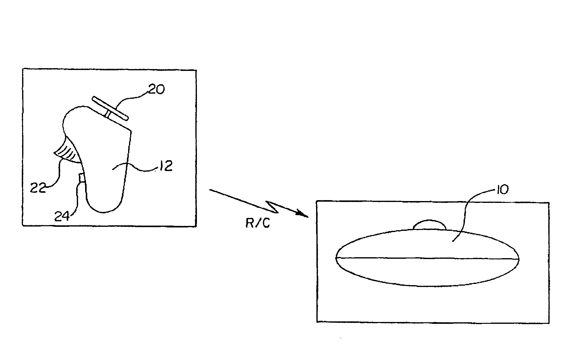
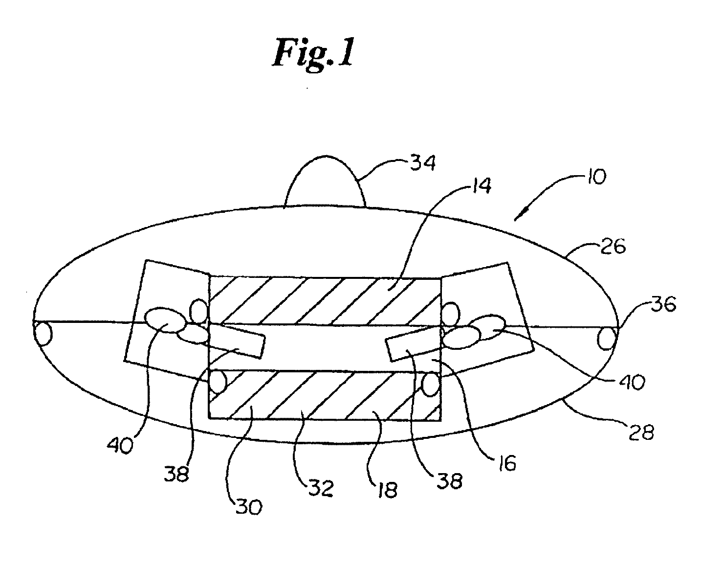
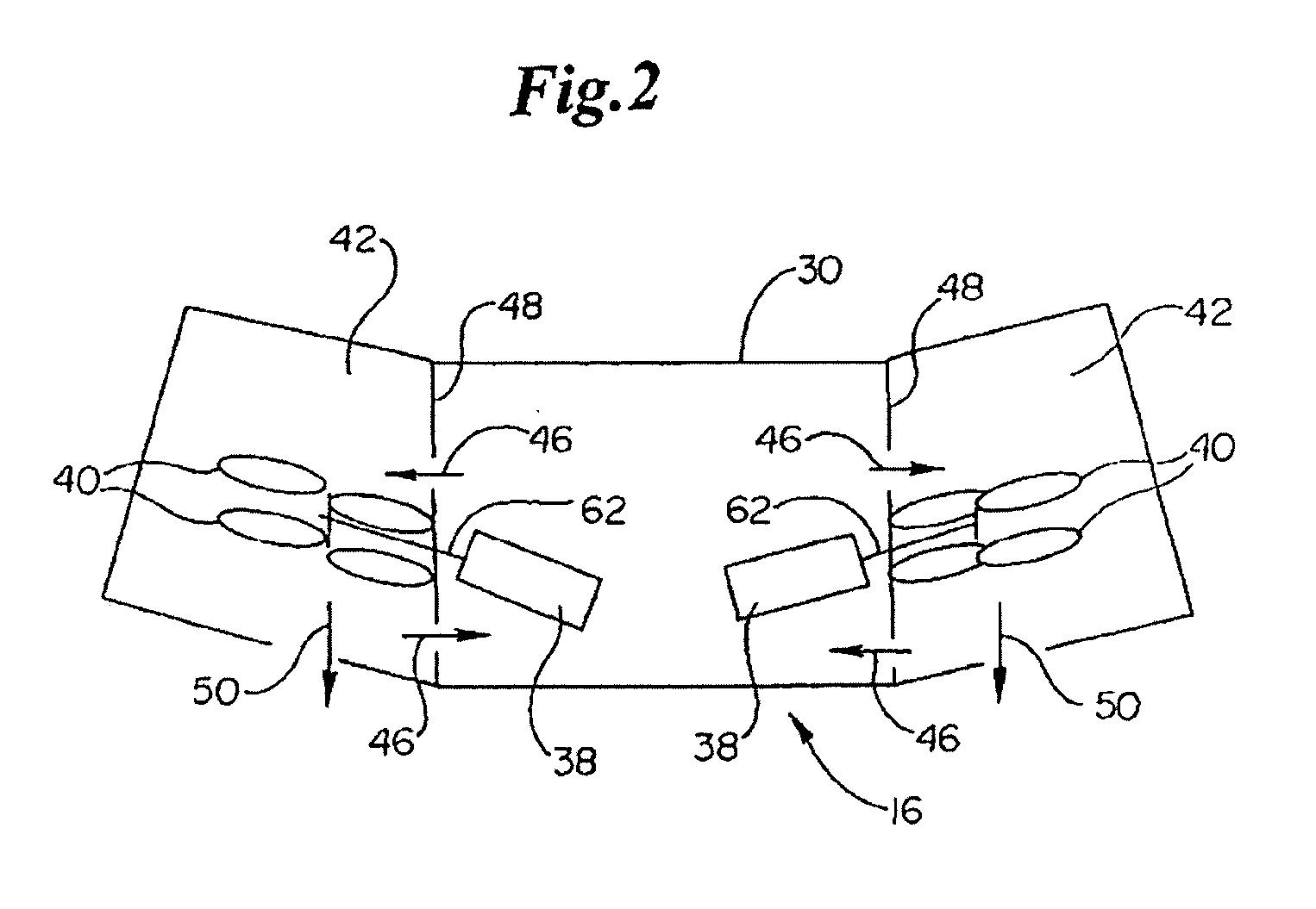
[0068]As illustrated in FIGS. 16-20, a preferred embodiment of a homeostatic flying hovercraft 200 is presented in accordance with the present invention. The homeostatic flying hovercraft 200 has generally an ellipsoid shaped body 200, having an upper surface 202 and bottom surface 204. As illustrated in FIG. 18, the upper surface 202 is comprised of a solid outer ring 206 of the saucer body 200 that extends radially inwards from the periphery and an removeable cover 208 containing a plurality of ventilation openings 210. Preferably, the cover 208 has a slightly greater curvature as compared to the outer ring 206. The lower surface 204, as illustrated in FIGS. 17 and 20 is a solid structure with four equally spaced circular duct openings 212. As illustrated in FIG. 19, each duct opening 212 preferably is angled at ten to fifteen degrees from the vertical and contains a battery-powered ducted fan 214 mounted inboard from the duct opening 212.

[0069]FIG. 21 provides a side cutaway view...


PUM


Abstract

A homeostatic flying hovercraft preferably utilizes at least two pairs of counter-rotating ducted fans to generate lift like a hovercraft and utilizes a homeostatic hover control system to create a flying craft that is easily controlled. The homeostatic hover control system provides true homeostasis of the craft with a true fly-by-wire flight control and control-by-wire system control.

Description

CROSS REFERENCE TO RELATED APPLICATIONS[0001]This application is a divisional application of application Ser. No. 10 / 526,153 which has the official 371(c) date of Jan. 26, 2006; which application is a US national stage application of the international application Serial Number PCT / US03 / 27415 filed Sep. 2, 2003; which application claims the benefit of provisional application Ser. No. 60 / 407,444 filed Aug. 30, 2002.FIELD OF THE INVENTION[0002]The present invention relates generally to the field of heavier-than-air aeronautical craft that are sustained in air by the force of a fluid such as air. More particularly, the present invention relates to a homeostatic flying hovercraft and to a radio controlled flying saucer toy employing the principals of a homeostatic flying hovercraft.BACKGROUND OF THE INVENTION[0003]Ever since the term “flying saucer” was first introduced in 1947, the concept of a circular flying craft has become a staple of popular culture. Unlike conventional aircraft in...

Claims


Application Information

Patent Timeline
Patent Type & Authority Applications(United States)
IPC IPC(8): B64C29/00B64C13/20B60V1/06B64C27/20
CPCB60V1/06B64C27/20B60V1/10G05D1/0858B64U30/00B64U30/20B64U50/19B64U2201/20B64C39/024G05D1/0022G05D1/0816B64C15/02B64C27/08B64D27/24G05D1/0016B64C39/001
Inventor SPIROV, PETERPEDERSEN, BRAD
Owner QFO LABS
Why Eureka
Try Eureka