Stepping motor and steel plate for manufacturing the stepping motor

a technology of stepping motor and steel plate, which is applied in the direction of magneto-mechanical circuits, instruments, horology, etc., can solve the problems of high precision, complex punching mechanism, and insufficient amount of facilities, so as to reduce iron loss and cogging torque of the stepping motor

Inactive Publication Date: 2008-09-18
HITACHI LTD
View PDF0 Cites 20 Cited by
  • Summary
  • Abstract
  • Description
  • Claims
  • Application Information

AI Technical Summary

Benefits of technology

[0026]According to the present invention, the iron loss and cogging torque of the stepping motor can be reduced.

Problems solved by technology

In punching the steel plates it is very difficult to punch out the rotor and stator simultaneously from the same area in the same steel plate since the gap size between the rotor and the stator is very small.
Because the punching die mechanisms are complicated and of high precision, a sufficient amount of investment for facilities is necessary.
However, the horning work may generate problems such as burrs or metal particles that may stick to the stator and / or rotor to thereby cause clogging in gaps after assembling the motor.
This would lower the yielding of the motor production.
There may arise another problem from horning.
Although frequent replacements of polishing grindstone may relieve the problem to some extent, a production cost may increase, which is not acceptable from the practical points of view.
There is another problem arising from the punching work.
The punching work generates a shearing stress to the steel plates, which causes the magnetic properties to be worse and generates iron loss.
Punching work deforms a crystalline structure in the sheared portions of the steel plates thereby to deteriorate magnetic properties thereof and to increase an area confined in a hysteresis curve, which leads to an increase in an iron loss.
Because thick electromagnetic steel plates have a large eddy current loss, efficiency of the hybrid type stepping motor is not good.
Since the precision of punching work is not good, cogging torque of the motor is not improved.

Method used


Image

  • Stepping motor and steel plate for manufacturing the stepping motor
  • Stepping motor and steel plate for manufacturing the stepping motor
  • Stepping motor and steel plate for manufacturing the stepping motor

Examples


Embodiment Construction

[0039]In the following an embodiment of the present invention will be explained.

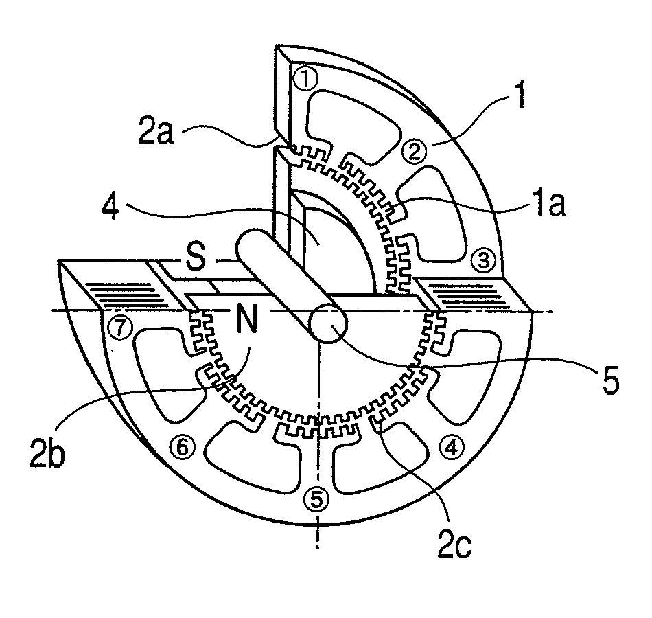
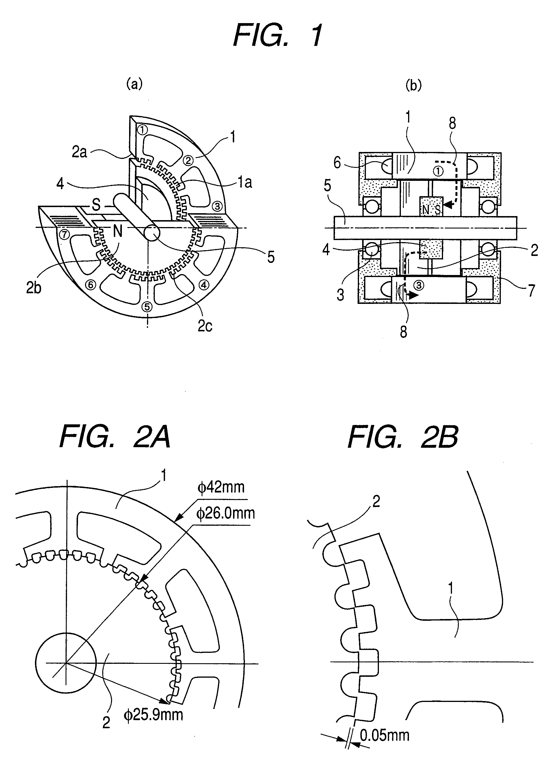
[0040]FIG. 1 shows structures of the most general, inner rotation type and two-phase hybrid type stepping motor whose basic step angle is 1.8 degrees. FIG. 1(a) shows a partially broken-away, perspective view and FIG. 1(b) shows a cross sectional view along the line A-O-A in FIG. 1(a). In the hybrid type stepping motor the stator and rotor are made of laminated steel plates. A minimum gap between the rotor and stator was as small as 30 to 50 μm, which is a value of the stepping motor capable of being produced. In FIG. 1(a), ①, ②, ③, ④, ⑤, ⑥, ⑦ and ⑧ designate the first pole, second pole, third pole, fourth pole, fifth pole, sixth pole, seventh pole and eighth pole, respectively.

[0041]The stator is provided with eight poles, which are arranged with a pitch of 45 degrees, each stator pole being provided with six small teeth with a pitch of 7.2 degrees, which are distributed to left and right from the cente...


PUM

PropertyMeasurementUnit
thicknessaaaaaaaaaa
thicknessaaaaaaaaaa
thicknessaaaaaaaaaa

Abstract

A stepping motor comprising:
a stator iron core with a plurality of salient poles each having a small tooth at the tip thereof and stator coils each disposed between the salient poles;
a rotor core with a plurality of teeth in the faces opposite to the stator; and
permanent magnets sandwiched by the rotor cores in an axial direction,
wherein the stator iron core and the rotor core are formed by laminated steel plates. The salient poles of the stator iron cores of the steel plates and small teeth are shaped by etching, and a thickness of the steel plates is 0.05 to 0.30 mm.

Description

CLAIM OF PRIORITY[0001]The present application claims priority from Japanese application Serial no. 2007-62752, filed on Mar. 13, 2007, the content of which is hereby incorporated by reference into this application.FIELD OF THE INVENTION[0002]The present invention relates to a stepping motor and a steel plate for manufacturing the stepping motor.RELATED ART[0003]A hybrid type stepping motor is generally utilized in office automation equipments such as printers, robots, or a driving motor for industrial equipments such as transporting apparatuses. Especially, the stepping motors are widely used for precise positioning. In particular, hybrid type stepping motors that utilized magnets and reluctance torque are used for high precision positioning. In order to performing the precise positioning, it is necessary to make a standard step angle small, which is a rotating angle per one pulse input.[0004]In order to make the basic step angle small, it is necessary to design that the number of ...

Claims


Application Information

Patent Timeline
Patent Type & Authority Applications(United States)
IPC IPC(8): H02K1/14H02K37/12H02K15/03B44C1/22
CPCH02K1/02H02K37/18H02K15/022H02K1/146
Inventor ENOMOTO, YUJIISHIKAWA, YOSHIHISAABE, TERUYOSHI
Owner HITACHI LTD
Why Eureka
Try Eureka