Charging and discharging control circuit and charging type power supply device
Inactive Publication Date: 2008-09-18
ABLIC INC
View PDF8 Cites 21 Cited by
Summary
Abstract
Description
Claims
Application Information
AI Technical Summary
This helps you quickly interpret patents by identifying the three key elements:
Problems solved by technology
Method used
Benefits of technology
Benefits of technology
[0013]It is an object of the present invention to provide a charging and discharging control circuit and a charging type power supply device capable of reducing current consumption even when a battery is in an overcurrent state.
[0016]In the present invention, when the battery is in the overcurrent state, a parasitic diode of the protection circuit does not cause a forward current to flow. As a result, a parasitic bipolar transistor of the protection circuit, which uses the forward current as a base current, is not activated, whereby the current consumption in the charging and discharging control circuit is prevented from increasing.
Image
Click on the blue label to locate the original text in one second.
Reading with bidirectional positioning of images and text.
Examples
first embodiment
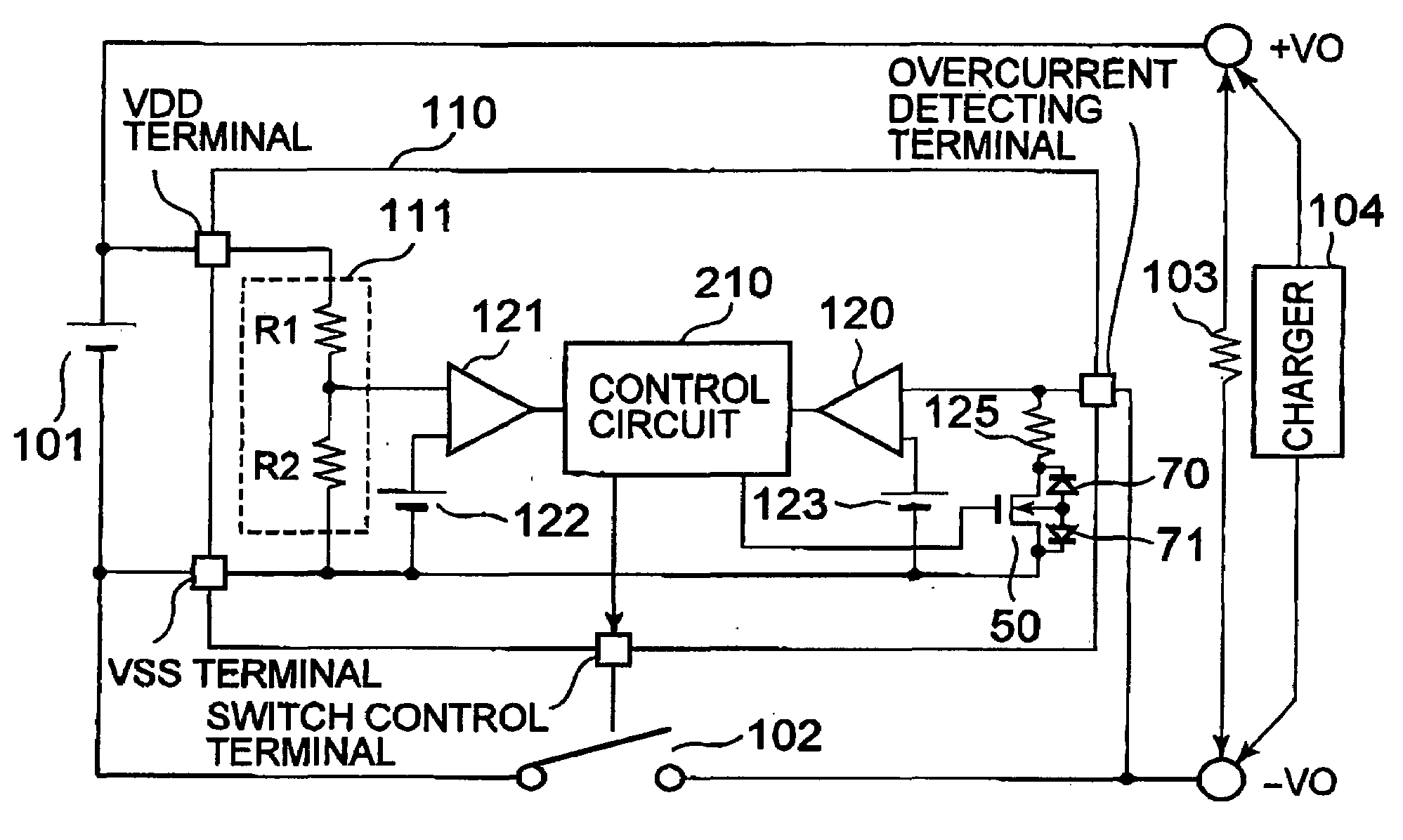
[0025]First, a configuration of a charging type power supply device according to a first embodiment of the present invention will be described. FIG. 1 is a diagram showing the charging type power supply device according to the first embodiment of the present invention.
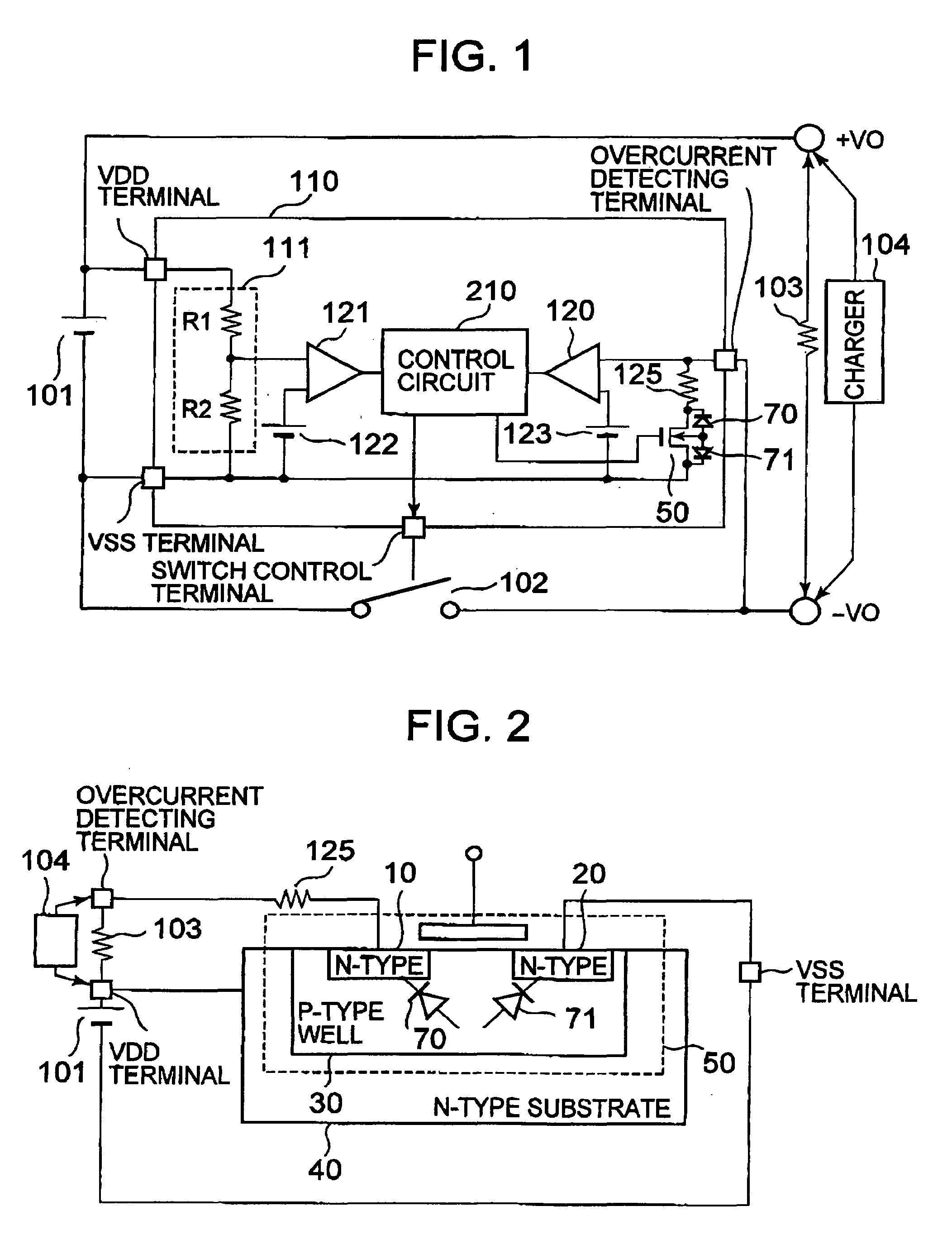
[0026]The charging type power supply device includes a battery 101, a charging and discharging control circuit110, and a switch 102. The charging type power supply device is connected to a charger 104 or a load 103. The charging and discharging control circuit 110 includes a voltage divider circuit 111 having a resistor R1 and a resistor R2, a reference voltage circuit 122, an overcharge detecting comparator 121, a control circuit 210, an overcurrent detecting comparator 120, a reference voltage circuit 123, a resistor 125, and a protection circuit 50 having a parasitic diode 70 and a parasitic diode 71.
[0027]In this case, a back gate of the protection circuit 50 is connected to a source thereof through the parasitic d...
second embodiment
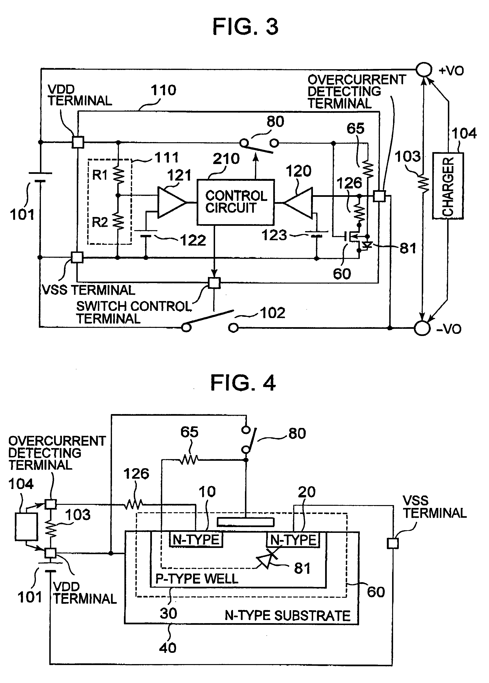
[0034]Next, a configuration of a charging type power supply device according to a second embodiment of the present invention will be described. FIG. 3 is a diagram showing the charging type power supply device according to the second embodiment.
[0035]As compared with the charging type power supply device of the first embodiment, in the charging type power supply device of the second embodiment, the resistor 125, the protection circuit 50, and the parasitic diodes 70 and 71 are not provided, and a switch 80, a resistor 65, a resistor 126, a protection circuit 60, and a parasitic diode 81 are additionally provided.
[0036]In this case, a back gate of the protection circuit 60 is connected to a source thereof through the parasitic diode 81, and is also connected to a gate thereof through the resistor 65. A gate of the protection circuit 60 is connected to the VDD terminal through the switch 80.
[0037]The control circuit 210 performs on / off control of each of the switch 80 and the switch 1...
PUM
Abstract
An overcharge detecting comparator (121) detects an overcharged state of a battery (101), and an overcurrent detecting comparator (120) detects an overcurrent state of the battery (101). In response to output signals from those comparators, a control circuit (210) performs on / off control of each of a switch (102) and a protection circuit (50). In response to an output signal from the control circuit (210), the protection circuit (50) is turned on, to thereby connect a resistor (125) to a path connecting a VSS terminal and an overcurrent detecting terminal, and is turned off, to thereby disconnect the resistor (125) from the path. As a result, even when the battery is in the overcurrent state, current consumption can be reduced.
Description
BACKGROUND OF THE INVENTION[0001]1. Field of the Invention[0002]The present invention relates to a charging and discharging control circuit that controls charging and discharging of a battery, and a charging type power supply device including the charging and discharging control circuit mounted thereto.[0003]2. Description of the Related Art[0004]A configuration of a charging type power supply device of a related art will be described. FIG. 5 is a diagram showing the charging type power supply device of the related art.[0005]The charging type power supply device includes a battery 101, a charging and discharging control circuit 110, and a switch 102. The charging type power supply device is connected to a charger 104 or a load 103. The charging and discharging control circuit 110 includes a voltage divider circuit 111 having a resistor R1 and a resistor R2, a reference voltage circuit 122, an overcharge detecting comparator 121, a control circuit 210, an overcurrent detecting compar...
Claims
Application Information
Patent Timeline
Application Date:The date an application was filed.
Publication Date:The date a patent or application was officially published.
First Publication Date:The earliest publication date of a patent with the same application number.
Issue Date:Publication date of the patent grant document.
PCT Entry Date:The Entry date of PCT National Phase.
Estimated Expiry Date:The statutory expiry date of a patent right according to the Patent Law, and it is the longest term of protection that the patent right can achieve without the termination of the patent right due to other reasons(Term extension factor has been taken into account ).
Invalid Date:Actual expiry date is based on effective date or publication date of legal transaction data of invalid patent.

