Protective cover for a sensor

a technology for protecting covers and sensors, applied in the field of control sensors, can solve the problems of not being able or desirable to provide a sensor housing, sensors also suffer from the same infirmities as the protectively housed sensors, and are subject to damage, etc., and achieve the effect of easy cleaning and/or replacement, and increasing the operational life of the control sensor

Inactive Publication Date: 2008-09-18
TURCK INC
View PDF4 Cites 4 Cited by
  • Summary
  • Abstract
  • Description
  • Claims
  • Application Information

AI Technical Summary

Benefits of technology

[0017]An object of the present invention is to protect the sensing surface of a control sensor so that it is able to resist harsh work environments.
[0018]It is another object of the present invention to increase the operational life of a control sensor.
[0019]A feature of the present invention is that it can be easily cleaned and / or replaced.

Problems solved by technology

However, in some instances, it is not possible or desirable to provide housing for the sensor.
These sensors also suffer from the same infirmities as the protectively housed sensors.
That is, they are also subject to damage from high temperatures, spatter, weld flash, harsh environments and the like.
Additionally, sensors may be subject to accidental impacts from a variety of sources, inadvertent contact with corrosive chemicals, or temperature extremes, all of which may shorten the operational life of the sensors.
For example, a sensor may be impacted and scratched by machinery that has become broken, bent or misaligned.
A sensor might become inoperable due to contact with highly reactive materials used during fabrication, or corrosive chemicals used during periodic cleaning.
In addition, the sensor might be exposed to ambient temperatures in excess of its designed operational range.
Of the aforementioned operational conditions, excessive heat, spattering, and weld flash are of the greatest concern because they cannot be easily ameliorated or eliminated.
In addition, GMAW can often produce spattering, which is usually generated by droplets of weld material that impact the workpiece, but which do not form part of the weld.
Unfortunately, for optimum operation, the sensor(s) usually are required to be positioned within the spatter and weld flash zones.
Thus, over time, even a sensor having a small surface area will be impacted by a significant amount of spatter and / or weld flash.
Excessive heat, spatter, and weld flash are particularly troublesome because the destructive effect they have on the sensing surfaces of the sensors.
When extraneous weld byproducts such as spatter or weld flash material impact a typical sensing surface comprised of glass reinforced thermoplastic or thermoset plastic they may bounce off harmlessly, but more often than not they form pits or become embedded in the material.
And, because this accretion is primarily metallic, it affects the operation of the sensor (which is usually designed to sense metallic objects).
That is, the spatter or flash may accumulate to the extent where it becomes detectable and it combines with the material to be welded to trigger the sensor prematurely.
As one may imagine, replacing such sensors can result in significant down time.
However, because of the thermoplastic's relatively low glass transition and melting points, they were susceptible to impacts by the larger bits of welding byproducts having higher levels of kinetic energy, which formed pits primarily by melting the material.
However, they were comparatively more brittle than the thermoplastics and were susceptible to pitting due to impacts of welding byproducts that knocked off fragments of the material.
However, these materials suffer from the same drawbacks as the above-mentioned thermoplastics and thermoset plastics.
That is, they are either too soft or too hard and do not solve the problems associated with weld flash, namely the accretion of weld material on the sensing surface of the sensor.

Method used


Image

  • Protective cover for a sensor
  • Protective cover for a sensor

Examples


Embodiment Construction

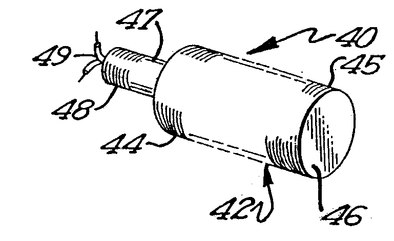
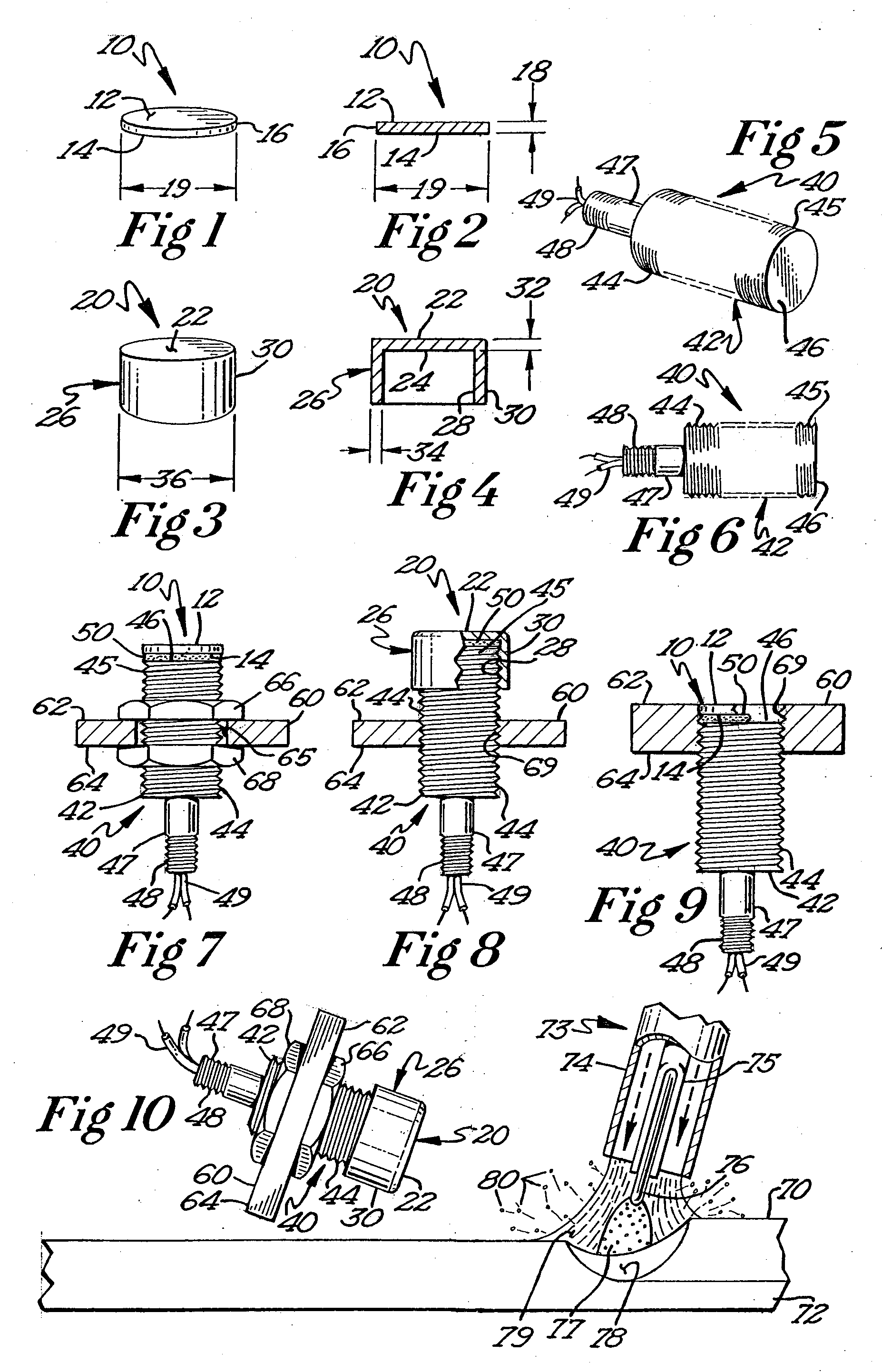
[0032]Referring to FIGS. 1 and 2, a preferred embodiment of the protective cover is depicted. The cover 10 includes a first surface 12 a second surface 14 and an edge 16. The cover 10 comprises a layer of material having one or more of the following characteristics: a preferred shore-A durometer hardness in the range of 60-90, a preferred tensile strength of 1320 psi (92.82 kilogram-force per square centimeter (kgf / cm2)) or greater, a preferred dielectric strength of around 300 volts / mil, and a preferred thermal conductivity of 0.3 to 0.5×10⁻³ cal / sec2, and a temperature stability of about −55 to +200 degrees Celsius. Preferably, the material comprises silicone. More preferably, the material comprises gray-colored silicone that can be molded under thermosetting conditions and later cut to shape. The thickness 18 of the cover, which is defined by the opposing surfaces 12 and 14, is configured so that it does not interfere with the operation of the sensor and yet offers protection fro...


PUM

PropertyMeasurementUnit
thicknessaaaaaaaaaa
thicknessaaaaaaaaaa
thicknessaaaaaaaaaa

Abstract

A protective cover for a sensing surface of a control sensor / proximity detector. The protective cover comprises a material having a preferred shore-A durometer hardness in the range of 60-90, a preferred tensile strength of 1320 psi (92.82 kilogram-force per square centimeter (kgf / cm2)) or greater, a preferred dielectric strength of around 300 volts / mil, and a preferred thermal conductivity of 0.3 to 0.5×1031 3 cal / sec2, and a temperature stability of about −55 to +200 degrees Celsius. The protective cover may be adhesively secured to the proximity detector so that the sensing surface is effectively covered. The protective cover may be in the form of a sheet or may be in the form of a cap. Preferably, the protective cover comprises silicone material.

Description

BACKGROUND OF THE INVENTION[0001]This invention relates generally to control sensors used in harsh operating conditions. More particularly, the present invention relates to a control sensor having an exterior surface that is provided with a protective cover that is resistant to high temperatures, weld flash, pitting, abrasion, acidic and caustic solutions, solvents, and the like.[0002]Robotics and automation have been used in manufacturing for many years. A typical use for robotics and automation is in the automotive manufacturing industry, and particularly in operations such as car body assembly. In such operations, welding is the preferred method of joining car body parts together because it produces consistent, predictable results and the assembled car bodies are not only stronger and better able to resist vibrations, they are less likely to develop squeaks and rattles as they age. Car body fabrication generally involves moving a chassis or platform along an assembly line past a ...

Claims


Application Information

Patent Timeline
Patent Type & Authority Applications(United States)
IPC IPC(8): B23K9/32
CPCG01S7/4813
Inventor EATON, WILLIAM
Owner TURCK INC
Why Eureka
Try Eureka