
High Impact Gate

a high-impact gate technology, applied in the field of security gates, can solve the problems of reducing the barrier effect, affecting the security of the gate, and insufficient approach,

Inactive Publication Date: 2008-09-18
EZI AUTOMATION
View PDF13 Cites 32 Cited by
  • Summary
  • Abstract
  • Description
  • Claims
  • Application Information

AI Technical Summary

Benefits of technology

[0006]It is an object of the invention to provide a high impact gate that is readily movable but provides high security.
[0011]The lower structure of the high impact gate can include a first end part mounted on a sliding mechanism and allowing the distal second end to be cantilevered such that the second end can extend at least partially over a roadway to prevent unauthorized entry and the sliding mechanism allows sliding out of the way for authorised entry along the roadway.
[0014]The invention provides a method of mounting a high impact gate, the method including providing a gate including a lower structure sized to take the impact of a vehicle, the lower structure formed by two spaced linear structures joined by cross bracing to form a high impact barrier; providing two sets of buttresses on either side of a roadway upon which high security authorized access is required; mounting the gate on a sliding mechanism extending between the two sets of buttresses such that the buttresses provide a strengthening aid for the high impact gate when the lower structure is struck and the buttresses provide a linear control of the sliding mechanism.

Problems solved by technology

Intruders include unwanted personnel, animals, and vehicles.
However they greatly reduce the barrier effect and usually rely on being merely a demarcation line requiring security personnel to patrol and form the effective control barrier.
Such an approach is not sufficient in these times.
However this patent only discloses the need for a collapsible structure in order to perform the impact security system.
The system does not allow ready opening in combination with high security.
Such a system therefore is not practical for high impact security systems.
However such a structure of restraining barrier is not acting as a security system as it readily allows smaller articles such as people to gain access to the restricted area.
Further, such net restraint systems do not provide a visual barrier that looks substantial and has a deterrent value and the system does not provide an effective barrier to a second vehicle that may follow behind the first which is restrained in the net.

Method used


Image

  • High Impact Gate
  • High Impact Gate
  • High Impact Gate

Examples


Embodiment Construction

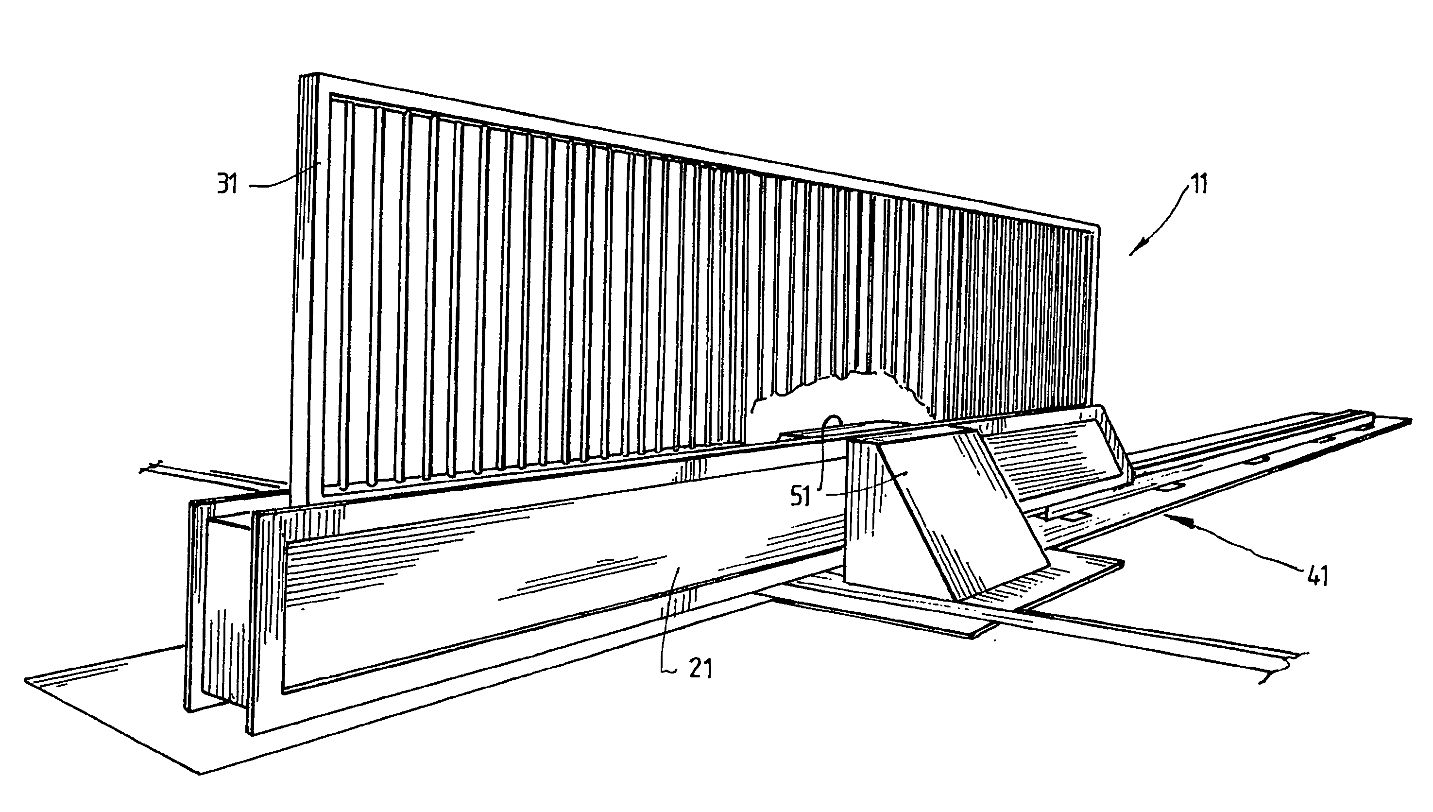
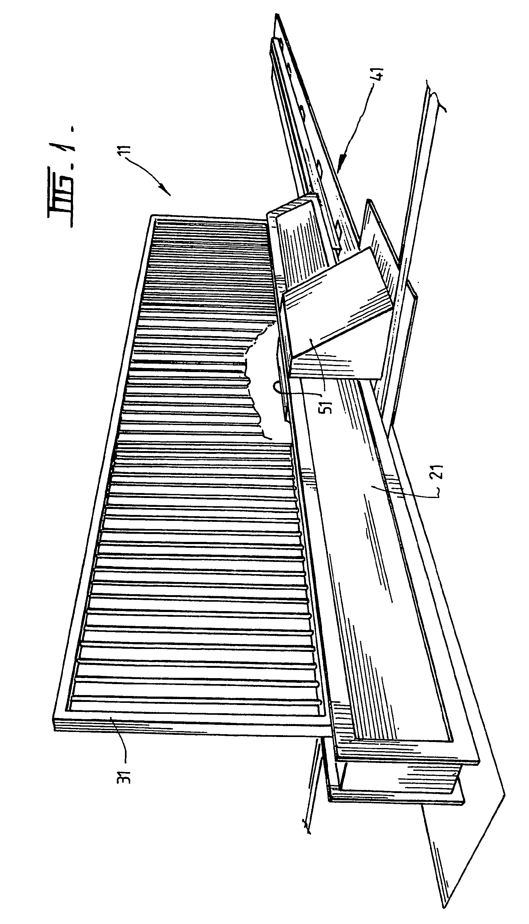
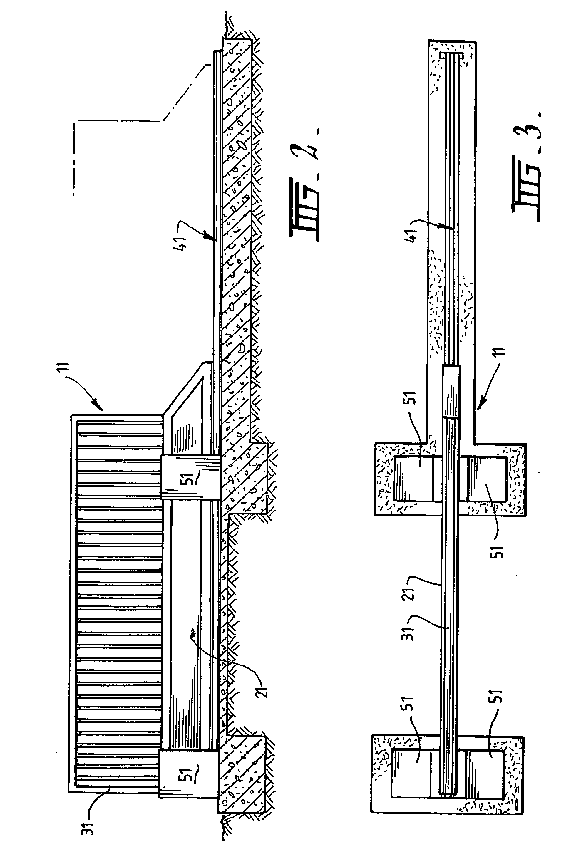
[0035]Referring to the drawings, there is shown a high impact gate system 11 including a lower reinforced elongated structure 21 and an upper barrier means 31. The lower structure 21 and barrier means 31 are sized to extend across a roadway.

[0036]Two spaced reinforcing means 51 are positioned to overlap respective end portions of the elongated structure 21 when the lower structure is in a closed position extending across the roadway. The two spaced reinforcing means 51 are two spaced sets of opposing buttresses closely fitting with the elongated lower structure. The reinforcing means 51 are able to provide supporting reinforcement to the elongated structure 21 providing the strength of the gate when receiving impact by vehicle or the like.

[0037]The lower reinforced elongated structure 21 and an upper barrier means 31 of the high impact gate system 11 are supported in cantilever manner by a foundation means 41 including a track to allow sliding movement of the gate. A control and dri...


PUM


Abstract

This invention relates to a security gate. It is particularly related to a high impact gate able to withstand significant direct impact of vehicles and maintain a secure location by prevention of access by vehicle or foot. There is provided a high impact gate system including a lower reinforced elongated structure and an upper barrier means sized to extend across a roadway, and two spaced reinforcing means able to be positioned to at least partially overlap respective end portions of the elongated structure when the lower structure is in a closed position extending across the roadway, the reinforcing means able to provide supporting reinforcement to the elongated structure when receiving impact by vehicle or the like.

Description

[0001]This invention relates to a security gate. It is particularly related to a high impact gate able to withstand significant direct impact of vehicles and maintain a secure location by prevention of access by vehicle or foot.[0002]Barriers of all types are used throughout the world to prevent intrusion into restricted areas or retain personnel or goods within restricted areas. Intruders include unwanted personnel, animals, and vehicles. At times personnel and goods must enter or leave restricted areas, resulting in the requirement for at least part of the barrier to be movable. Movable barriers, such as gates, doors, and movable portions of walls, allow passage out of and into restricted areas. However they greatly reduce the barrier effect and usually rely on being merely a demarcation line requiring security personnel to patrol and form the effective control barrier. Such an approach is not sufficient in these times.[0003]In granted U.S. Pat. No. 4,828,424 there is shown a vehi...

Claims


Application Information

Patent Timeline
IPC IPC(8): E01F13/04E06B11/04
CPCE06B11/045E01F13/048
Inventor PHILLIPS, RONALD WILLIAMPHILLIPS, IAN GREGORY
Owner EZI AUTOMATION
Learn More