
Method for tracking credit card fraud

a credit card fraud and fraud detection technology, applied in the field of credit card fraud detection methods, can solve the problems of identity theft and misrepresentation, fraud still occurs, and fraud still occurs,

Active Publication Date: 2008-09-18
VISA INT SERVICE ASSOC
View PDF10 Cites 119 Cited by
  • Summary
  • Abstract
  • Description
  • Claims
  • Application Information

AI Technical Summary

Benefits of technology

[0018]Another object of the present invention is to provide systems and methods to reduce incidences of fraud by validating users in a particular location where they are performing some automated activity requiring access to a secure system. This object of the present invention is achieved by determining the proximity between a wireless device's location and the wireless device user's location and providing those proximity results to a results processing system. Based on the resultant proximity, users accessing the automated system may be determined to be valid or not.

Problems solved by technology

Today, many employed technologies have greatly reduced fraudulent transactions, but instances of fraudulent activity still occur.
However, even with these and many other technologies employed, fraudulent activity still occurs and identity theft and misrepresentation remains a problem.
In addition, many existing fraud detection and prevention technologies can and do provide a false positive indication of fraudulent activity.
If the individual's behavior when engaging in a secure activity is not consistent with that individual's past behavior, a likelihood of fraudulent activity may be deduced.
This behavior may appear anomalous to a fraud detection system and the activity or transaction being performed may be terminated before any potential fraud is perpetrated.
If this is in fact a false positive indication and the individual is actually an authorized user, the user suffers the consequences of a failed transaction and the service provider is perceived to have provided a poor quality of service.
Also, debit or credit cards may be stolen, PINs may become compromised and information meant to be held only by authorized users may become known to others.
These methods are not optimal as fraudulent activity may be successful in at least one instance prior to detection and subsequent prevention.
No fraud detection and prevention system is perfect and there is always a need to employ additional technologies to further reduce fraud and identity theft, thereby reducing the economic impact of such undesired activity.

Method used


Image

  • Method for tracking credit card fraud
  • Method for tracking credit card fraud
  • Method for tracking credit card fraud

Examples


Embodiment Construction

[0020]Features and advantages of the present invention will become apparent to those skilled in the art from the following description with reference to the drawings. Embodiments of the present invention are illustrated by way of example, and not limitation, in the figures of the accompanying drawings, and in which like references indicate the same or similar elements.

[0021]In the drawings,

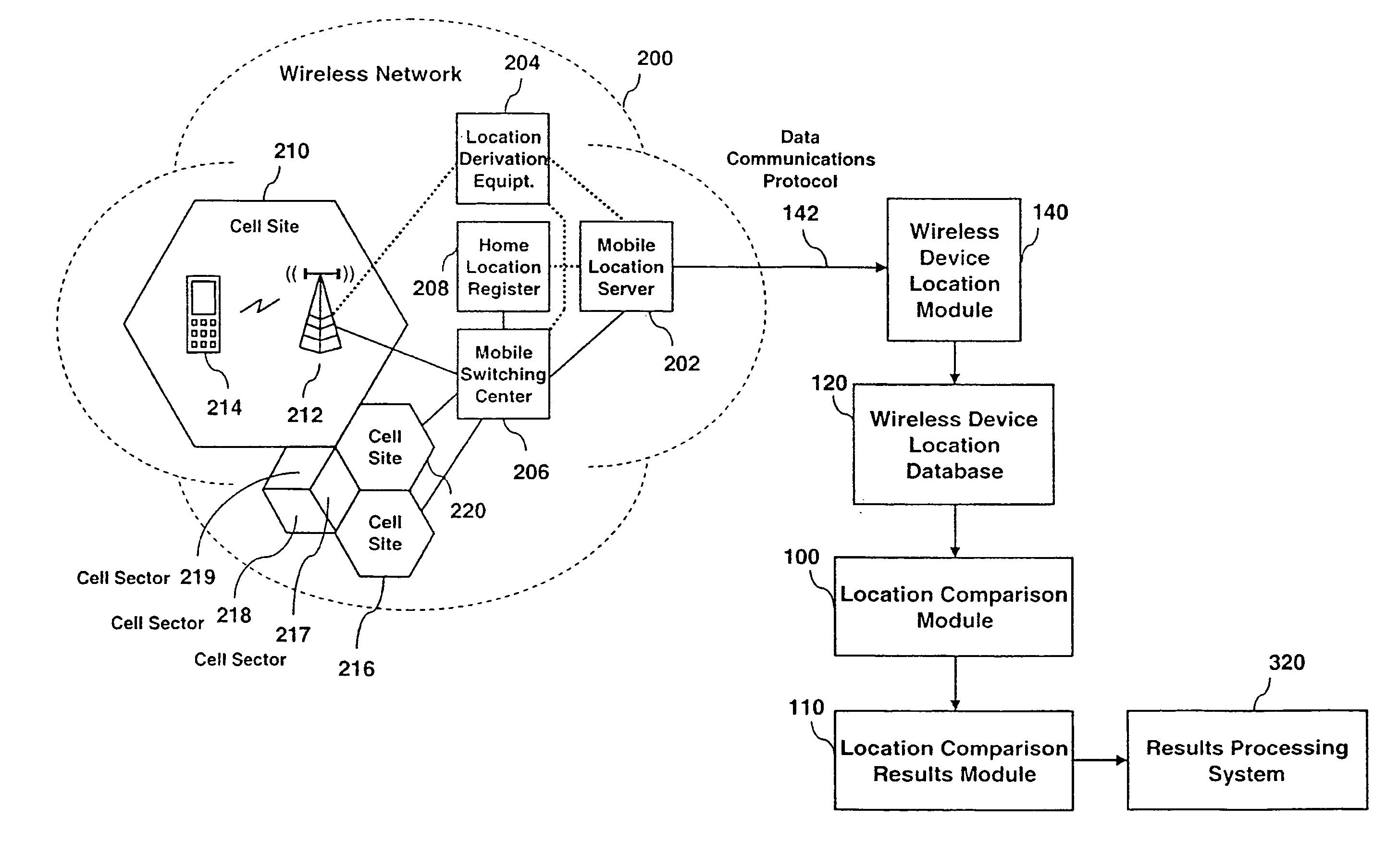
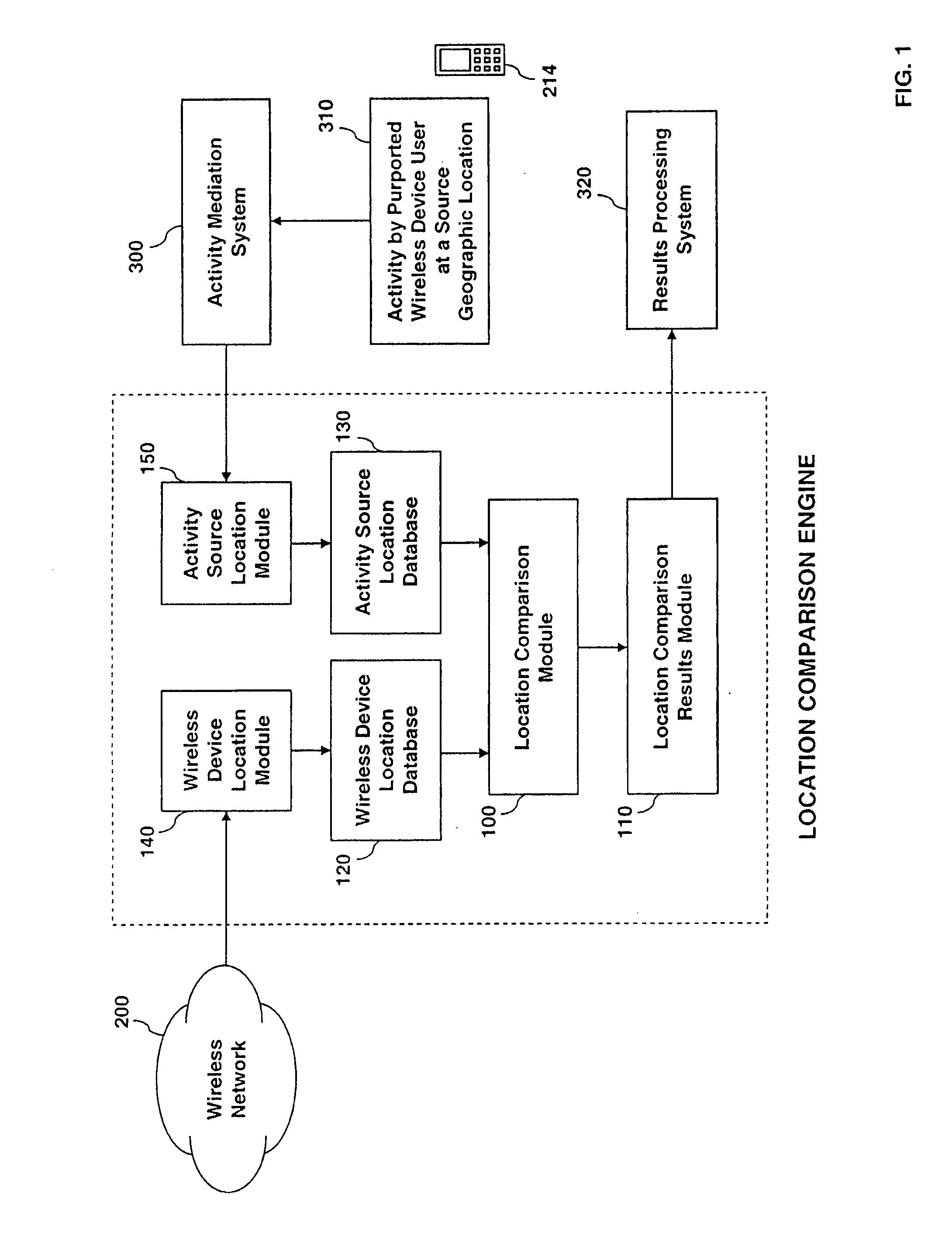
[0022]FIG. 1 depicts the functional entities and modules of an example Location Comparison Engine. Included in the depiction is example connectivity to a Wireless Network, an Activity Mediation System, a Results Processing System, a Wireless Device Location Database, an Activity Source Location Database, a Location Comparison Module, and a Location Comparison Results Module, in accordance with the principles of the present invention.

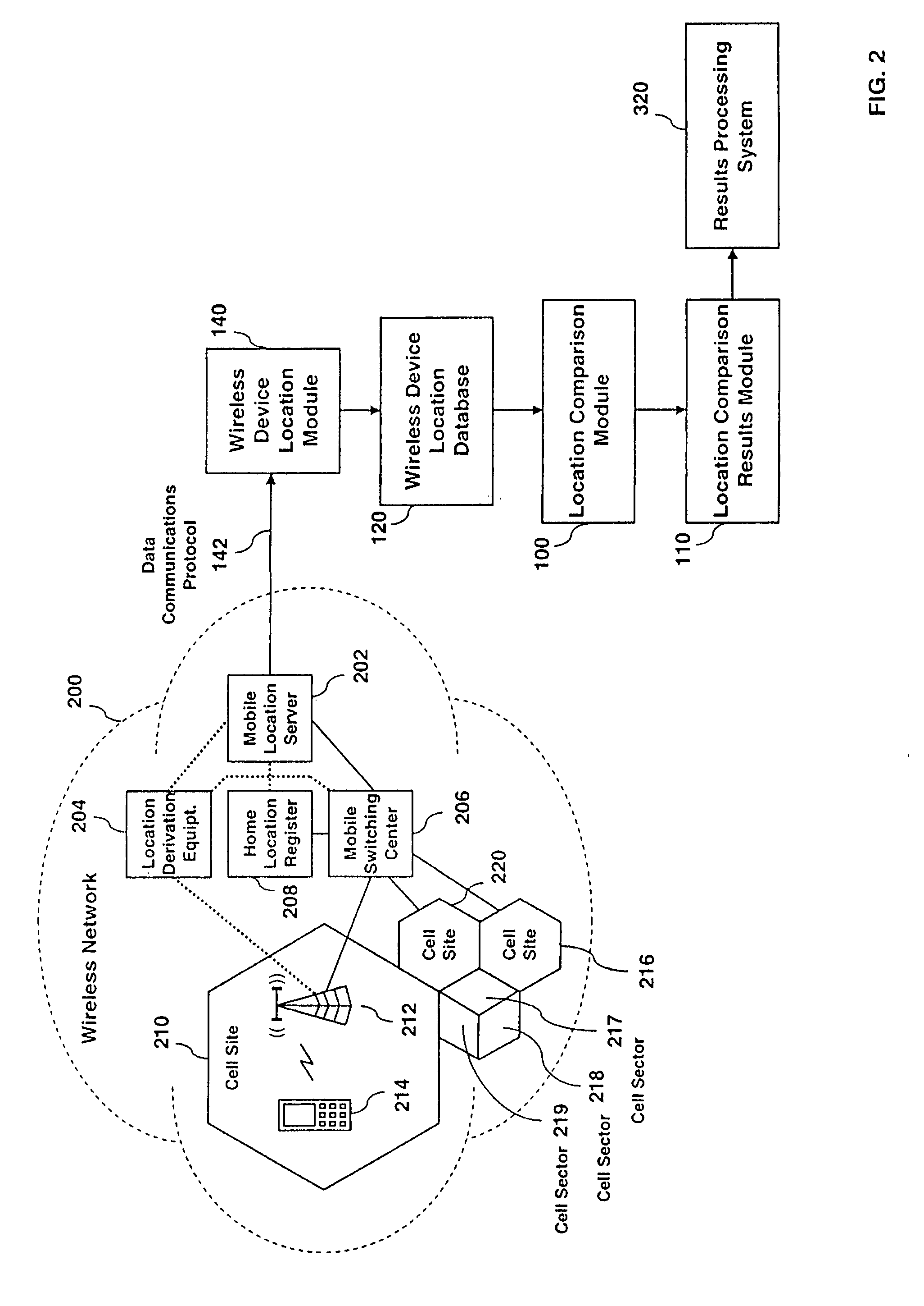
[0023]FIG. 2 shows exemplary connectivity of a Wireless Network to the Wireless Device Location Module and the concerned functional entities of an exemplary Wireless N...


PUM


Abstract

A system and method for automatically comparing obtained wireless device location information from a wireless network and comparing that location with another independent source geographic location is provided. Location information is derived from two or more sources in a multiplicity of ways and a comparison is made within a Location Comparison Engine. The Location Comparison Engine makes use of databases that assist in resolving obtained raw positioning information and converting that positioning information into one or more formats for adequate location comparison. Results of the location comparison are deduced to determine if the wireless device is in some proximity to some other activity source location. Other location information used for comparison may be obtained from a multiplicity of sources, such as another network based on some activity of the wireless device user, another wireless device via a wireless network, or any system capable of providing location information to the Location Comparison Engine.

Description

CROSS-REFERENCE TO RELATED APPLICATIONS[0001]This application is claims the benefit of U.S. Ser. Nos. 60 / 895,144 filed Mar. 16, 2007, 60 / 909,716 filed Apr. 3, 2007 and 60 / 979,663 filed Oct. 12, 2007, all of which applications are incorporated herein by reference.BACKGROUND OF THE INVENTION[0002]1. Technical Field of the Invention[0003]The present application primarily relates generally to systems and methods directed to location-based services within a wireless telecommunications or data communications network, and more particularly to other technical fields such as technologies used to authenticate secure transactions, technologies to verify and validate user identities and for use with any application where the results of comparing two or more geographic locations has some utility or value.[0004]2. Background of Related Art[0005]Wireless device location information is necessary for the operation of cellular telecommunications services. This location information enables calls to be...

Claims


Application Information

Patent Timeline
IPC IPC(8): H04Q7/20H04W4/021H04W12/06
CPCH04W12/06G06Q20/3224H04W12/12H04W4/021H04W4/023H04W4/008H04W12/63G07F9/001G06Q20/384
Inventor DANKAR, AJAYREDDY, SUNITAMORTIER, MICHAEL P.BUHRMANN, MICHAEL F.DENNIS, CHARLES L.SNYDER, RANDALL A.
Owner VISA INT SERVICE ASSOC
Learn More