Soft body catheter with low friction lumen

Inactive Publication Date: 2008-09-18
HOLOGIC INC
View PDF63 Cites 24 Cited by
  • Summary
  • Abstract
  • Description
  • Claims
  • Application Information

AI Technical Summary

Benefits of technology

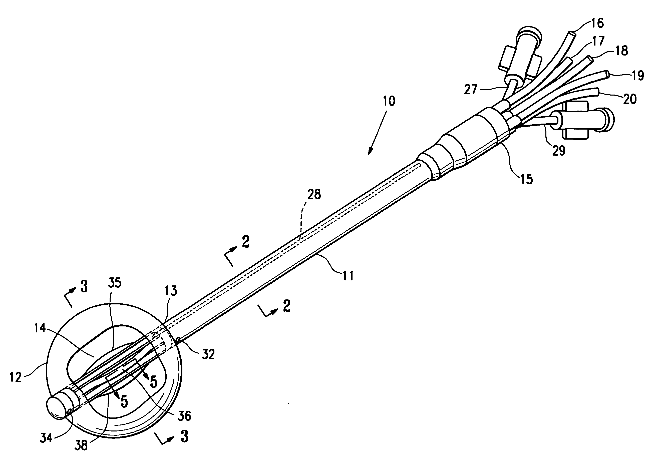
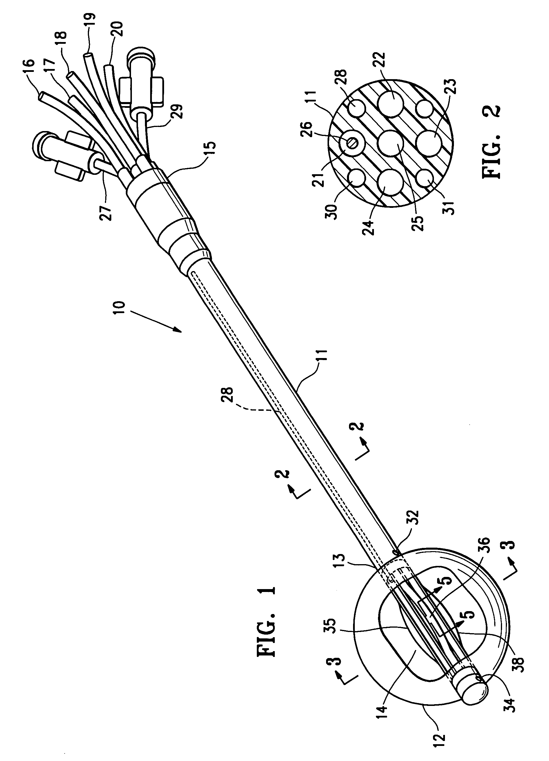
[0009]More specifically, an elongated catheter device embodying features of the invention includes a flexible elongated shaft, a treatment location at a distal portion of the device, at least one lumen extending within the shaft to the treatment location which is configured to receive or which includes a radiation source. Preferably, the catheter has an inflatable cavity filling member or balloon surrounding the treatment location on the distal portion of the catheter. In this embodiment, the flexible elongated shaft is formed of relatively low durometer polymeric material, e.g. 70A to about 25D Shore Hardness, to provide flexibility. At least one, and preferably a plurality of the inner lumens are provided with a lining of relatively high durometer polymeric material, e.g. 40D to 80D Shore Hardness. The relatively low durometer polymeric material for the elongated shaft is preferably a thermoplastic elastomer such as polyuret

Problems solved by technology

Tissue cavities resulting from biopsy or other surgical procedures such as lumpectomy typically are not always uniform or regular in their sizes and shapes, so that radiation treatment often result in differences in dosages applied to different regions of surrounding tissue, including “hot spots” and regions of relatively low dosage.
However, in order to facilitate folding or coiling the catheter shaft, the shaft must be fairly flexible or it will be difficult to maintain in the folded or coiled configur

Method used


Image

  • Soft body catheter with low friction lumen
  • Soft body catheter with low friction lumen
  • Soft body catheter with low friction lumen

Examples


Example

EXAMPLE I

[0023]About 1.4 grams of a high durometer polyester polyurethane polymer (Pellethane™) having a durometer hardness of 65D Shore was dissolved in 90 ml of tetrahydrofuran which is a non-aqueous solvent. A flexible catheter shaft having a plurality of lumens and formed of relatively low durometer polyurethane was positioned vertically with the lower lumen openings closed off by a plug as shown in FIG. 4A. One or more lumens were filled with the solution of tetrahydorfuran and polyurethane polymer, the plugs removed and the solution gravity drained from the lumens. The solution remaining on the surface of the lumens was allowed dry, evaporating the solvent and leaving the high durometer polyurethane solute tenaciously lining the lumens. The lumens lined with the high durometer polyurethane material had lower friction coefficients than the lumens of the tubular member before lining with high durometer polyurethane. Brachytherapy seeds could be readily advanced through the lined...

Example

EXAMPLE II

[0024]About 1.2 grams of a high durometer polyester polyurethane polymer (Pellethane™) having a durometer hardness of 55D Shore was dissolved in 80 ml of tetrahydrofuran which is a non-aqueous solvent. Eight grams of finely divided starch was mixed into the solution to form a slurry. A lumen of a flexible catheter shaft formed of relatively low durometer polyurethane was lined with the slurry of tetrahydorfuran, polyurethane polymer and particulate starch and allowed dry, evaporating the solvent and leaving the high durometer polyurethane solute and particulate tenaciously lining the lumens. The lumens lined with the high durometer polyurethane and starch particulate. Brachytherapy seeds could be readily advanced through the lined lumens, whereas advancement through the lumens before the application of the lining was difficult.

[0025]If desired, a colorant such as an ink, dye or pigment may be added to the polymeric coating to aid in identifying one or more lumens. Friction...


PUM

PropertyMeasurementUnit
Fractionaaaaaaaaaa
Diameteraaaaaaaaaa
Diameteraaaaaaaaaa

Abstract

The disclosure is directed to radiation catheter devices, methods for controlled application of irradiation to tissue at a body site, such as a cavity formed after removal of tissue, e.g. cancer, using such radiation catheter devices, solutions for forming a more lubricious luminal surface and method for lining lumens of such devices to improve the frictional characteristics thereof. The catheter device includes a flexible elongated shaft which is formed of low durometer polymeric material, which can be readily folded or coiled for securing the shaft to or under the skin of the patient and a radiation lumen lined with high durometer polymeric material and finely divided particulate to improve the frictional characteristics. The elongated shaft has at least one inner lumen for receiving a radiation source which has a layer of high durometer polymeric material that provides lower surface friction to facilitate advancement of a radiation source therein.

Description

RELATED APPLICATIONS[0001]This application is a continuation-in-part of application Ser. No. 11 / 724,578 filed Mar. 15, 2007 which is incorporated herein in its entirety by reference and from which priority is claimed.FIELD OF THE INVENTION[0002]This invention relates generally to the fields of medical treatment devices and methods of use. In particular, the invention relates to devices and methods for irradiating tissue surrounding a body cavity, such as a site from which cancerous, pre-cancerous, or other tissue has been removed.BACKGROUND OF THE INVENTION[0003]In diagnosing and treating certain medical conditions, it is often desirable to perform a biopsy, in which a specimen or sample of tissue is removed for pathological examination, tests and analysis. A biopsy typically results in a biopsy cavity occupying the space formerly occupied by the tissue that was removed. As is known, obtaining a tissue sample by biopsy and the subsequent examination are typically employed in the dia...

Claims


Application Information

Patent Timeline
IPC IPC(8): A61M36/04A61F2/958
CPCA61L29/085A61N5/1015A61M2025/0047
Inventor JONES, MICHAEL L.LOUW, FRANK R.
Owner HOLOGIC INC
Why Eureka
Try Eureka