
Storage locker

a storage locker and locker technology, applied in special buildings, tents/canopies, building components, etc., can solve the problems of difficult modification of relatively expensive locker construction using framing, etc., and achieve the effect of easy modification, less manufacturing cost, and convenient and inexpensive modification

Inactive Publication Date: 2008-09-25
COGAN WIRE & METAL PRODS
View PDF29 Cites 29 Cited by
  • Summary
  • Abstract
  • Description
  • Claims
  • Application Information

AI Technical Summary

Benefits of technology

[0006]It is the purpose of the present invention to provide storage lockers which are easier to construct and less expensive to manufacture. It is another purpose of the present invention to provide storage lockers which can be easily and inexpensively modified during construction to accommodate building construction anomalies where the lockers are to be located.
[0010]The storage lockers can also be closed with roofs of the same wire mesh panelling used in the walls if needed. The wire mesh wall panels are normally made for roofs eight feet high, the panels sized to leave some space between the ceiling of the storage area and the top of the panels when installed but not enough to provide entry into the locker over the panels. However, there are storage areas in buildings with ceilings ten feet high or even higher that are used for storage locker locations. In these areas the lockers can be provided with wire mesh roofs to close off the top of the lockers and thus prevent entry into the lockers over the top of the locker walls.

Problems solved by technology

Locker construction using framing is however relatively expensive.
Locker construction using framing is also difficult to modify to adapt the locker walls to uneven floors and walls and to pipes and ductwork close to the ceiling of the room containing the lockers.

Method used


Image

  • Storage locker
  • Storage locker
  • Storage locker

Examples


Embodiment Construction

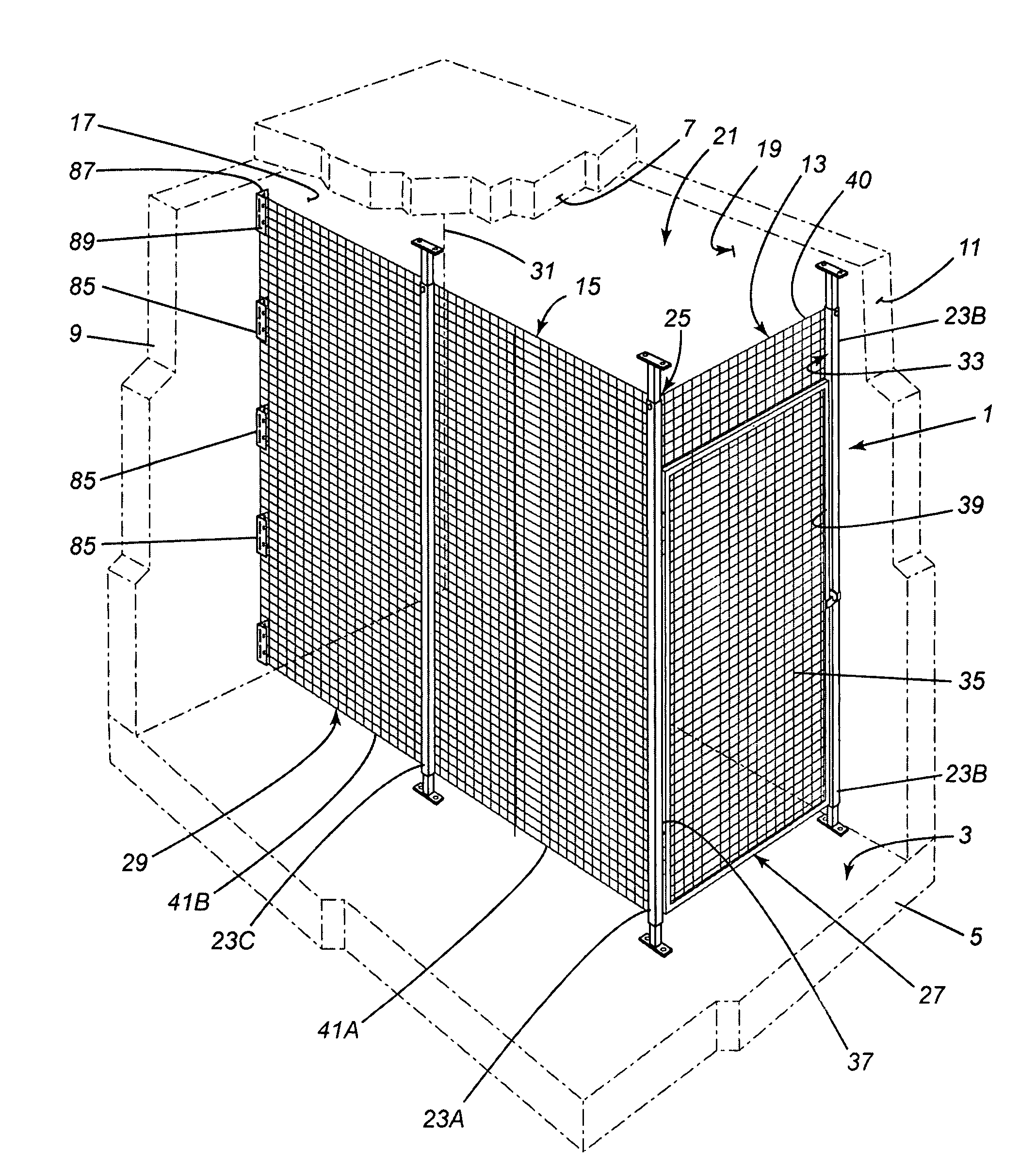
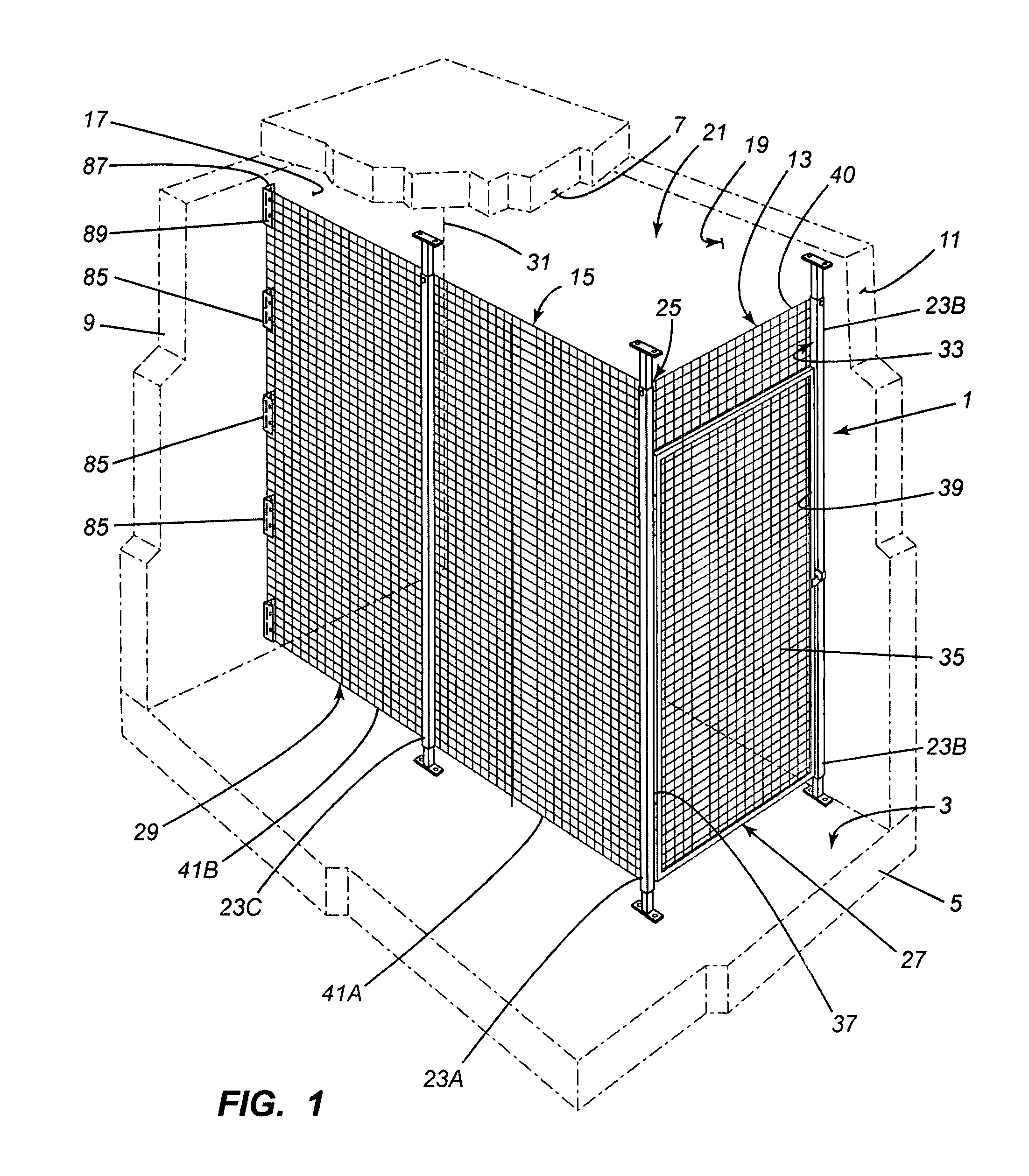
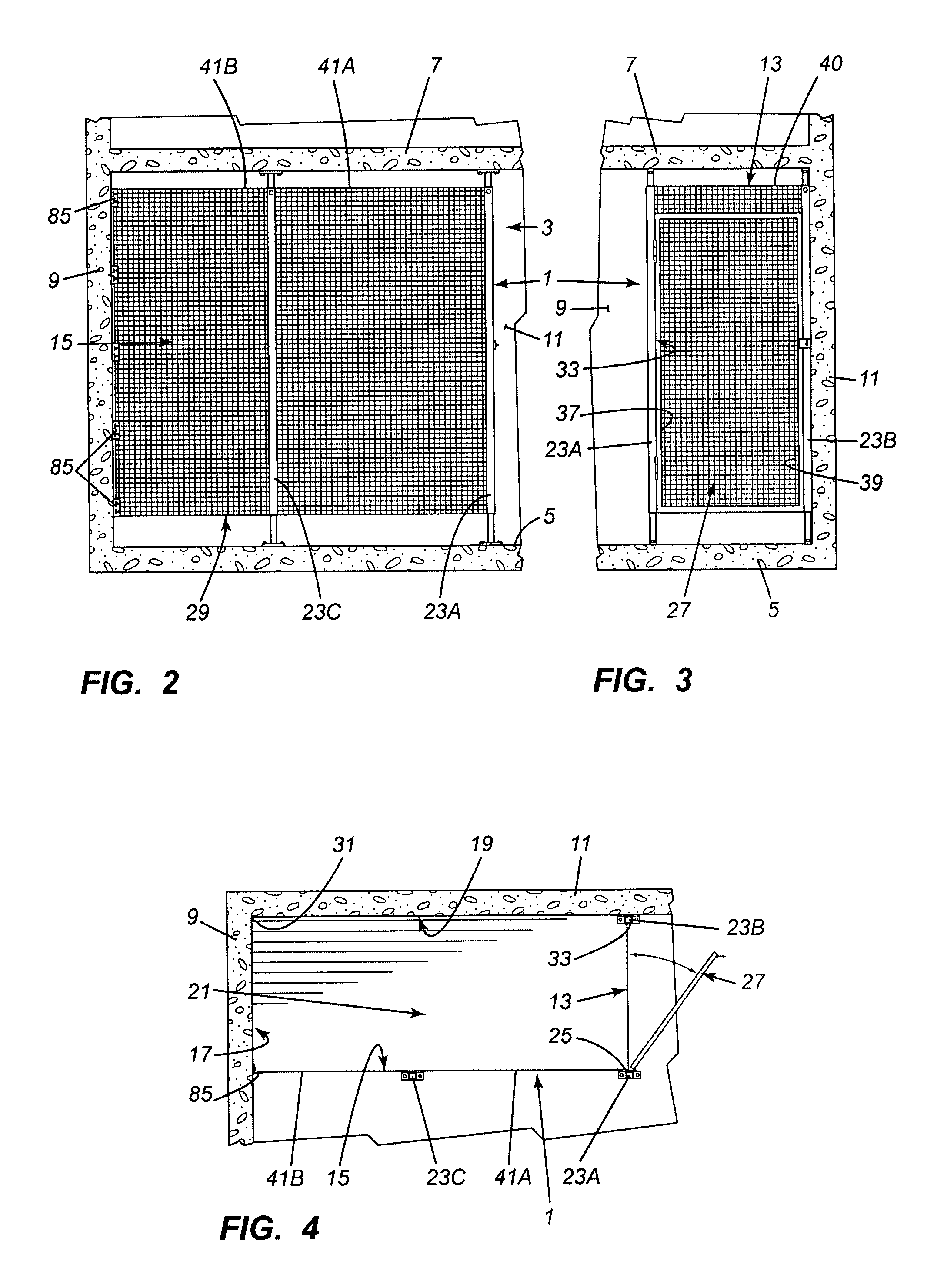
[0032]The locker 1 is adapted to be built in a storage area 3 such as in the basement of an apartment and / or condominium building. As shown in FIGS. 1 to 4, the storage area 3 in the building is defined by a floor 5, a ceiling 7, and walls, two walls 9, 11 of which are shown. The locker has at least four straight walls 13, 15, 17, and 19 joined to define a storage space 21. The floor area of the locker 1 defined by the walls 13, 15, 17 and 19 is usually rectangular but it could have a square or irregular shape as well.

[0033]At least two adjacent walls 13, 15 of the locker 1 have spaced apart posts 23A, 23B, 23C extending between the floor 5 and ceiling 7 of the storage area 3. The posts are identical. The posts are spaced apart a standard distance, such as four feet for example. The posts are preferably adjustable in length as will be described and are fastened to both the floor 5 and ceiling 7. The walls 13, 15 are normally perpendicular to each other and joined at a first corner 2...


PUM


Abstract

A storage locker in a building space, the building space having a floor, a ceiling and walls bounding the space between the ceiling and floor. The storage locker has at least four walls defining a storage space in the building space, first and second walls forming a first corner. At least the first and second walls each have spaced-apart posts extending between, and mounted to, the floor and ceiling, one of the posts at the first corner and common to the first and second walls. One of the first and second walls has a closure therein mounted between two of the posts forming the wall. At least the other wall has self-supporting wire mesh panelling extending over the length of the wall and mounted on the posts including the corner post to close the wall.

Description

CROSS-REFERENCE TO RELATED APPLICATIONS[0001]This application claims the priority of Canadian application no. 2,582,839, filed Mar. 22, 2007, and which is incorporated herein by reference.BACKGROUND OF THE INVENTION[0002]1. Technical Field[0003]This invention is directed toward a storage locker.[0004]2. Background Art[0005]Storage lockers are presently constructed with walls composed of wood or metal framing covered with panels of material to close in the locker storage space. The lockers are usually built against a wall of a building containing the lockers to have the building wall form the back wall of the locker. Adjacent lockers have a common side wall. The framing is rigid enough to define the shape of the locker. Locker construction using framing is however relatively expensive. Locker construction using framing is also difficult to modify to adapt the locker walls to uneven floors and walls and to pipes and ductwork close to the ceiling of the room containing the lockers.SUMM...

Claims


Application Information

Patent Timeline
IPC IPC(8): E04B1/00
CPCE04H1/125E04B2/7453
Inventor GODDARD, DEREK
Owner COGAN WIRE & METAL PRODS
Learn More