
Fuel lance

a fuel lance and oxidator technology, applied in the field of lance, can solve the problems of increasing pollutant emission, poor mixing through, and relatively unfavorable combustion reactions, and achieve the effect of improving the cooling action of the oxidator flow

Inactive Publication Date: 2008-09-25
ALSTOM TECH LTD
View PDF8 Cites 1 Cited by
  • Summary
  • Abstract
  • Description
  • Claims
  • Application Information

AI Technical Summary

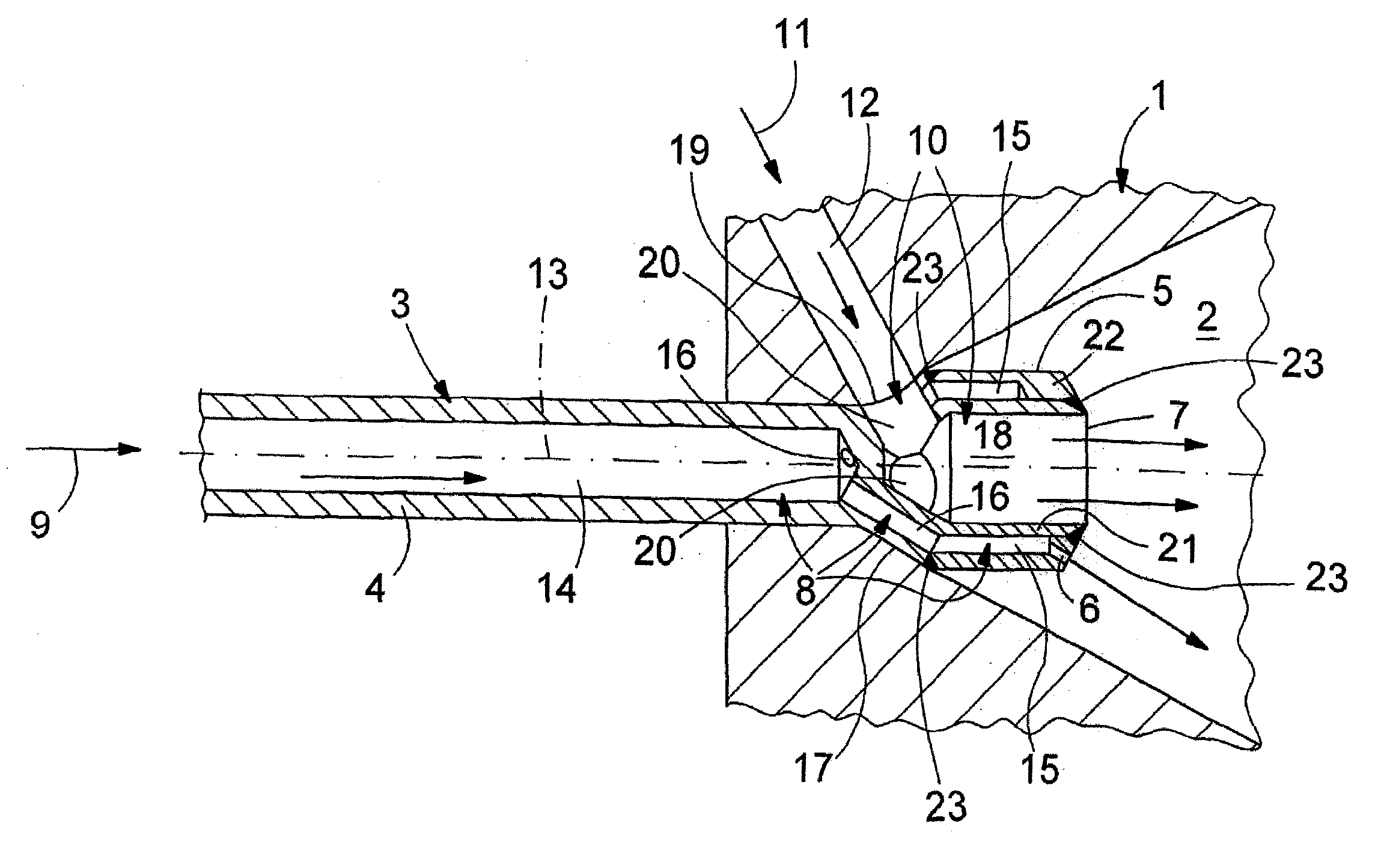
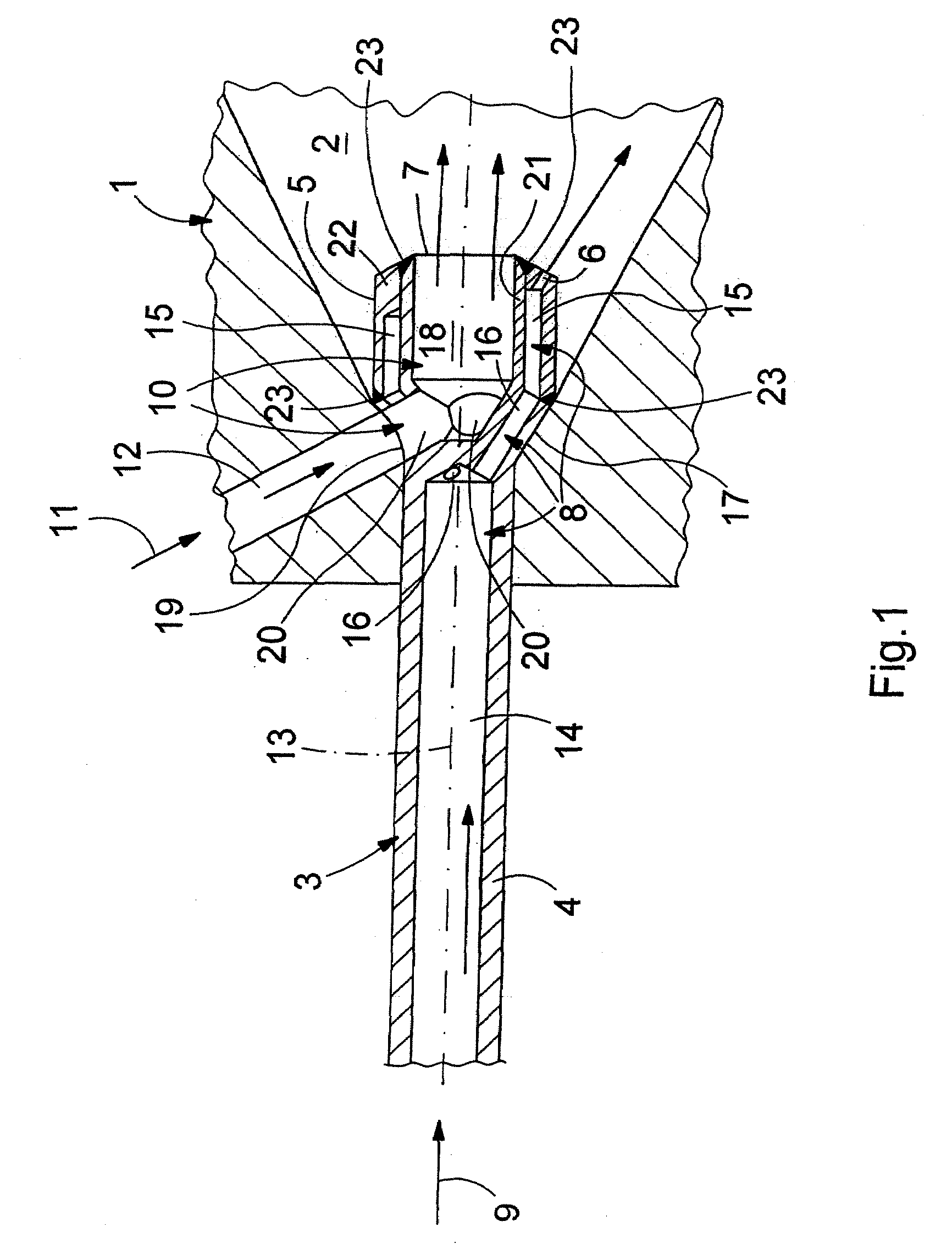
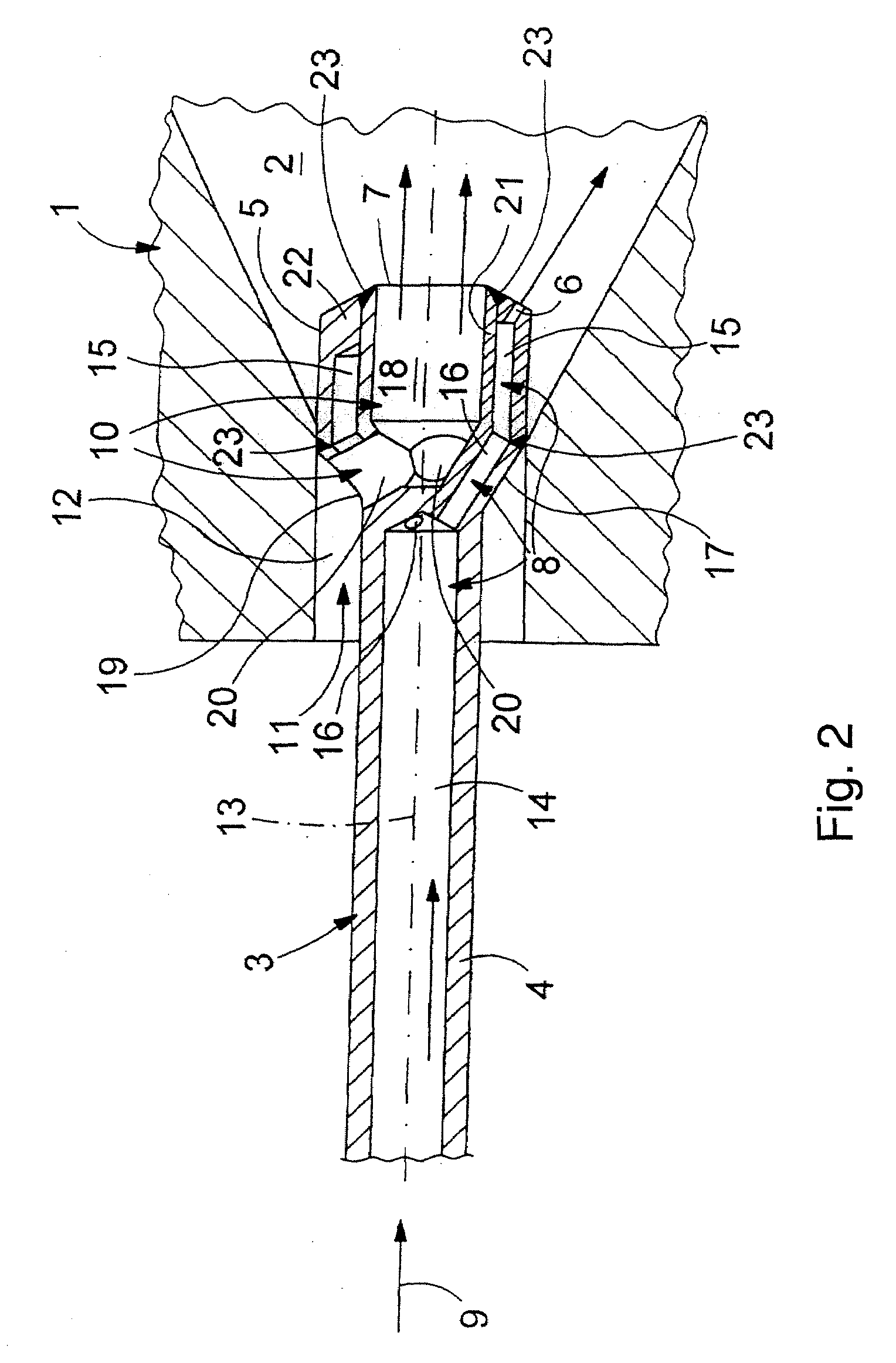
Benefits of technology

[0010]It has been shown that these measures lead to an improved mixture formation and to an improved combustion reaction, and, therefore, lead to reduced pollutant emissions. At the same time, however, the cooling and purging function of the centrally supplied oxidator is maintained.
[0012]Also advantageous are embodiments in which the oxidator feed has an oxidator chamber located centrally in the lance head, the end of which, which is open towards the combustion chamber, forms the oxidator outlet orifice. Furthermore, a plurality of oxidator connecting passages can be provided, which in each case connect the oxidator chamber to an oxidator inlet orifice which is located radially on the outside on the lance head. By inclusion of the oxidator chamber, a relatively large surface which is impactable by the oxidator is provided inside the lance head, which improves the cooling action of the oxidator flow.

Problems solved by technology

In larger burners of this type, therefore burners with larger output or larger fuel conversion, as the case may be, it has been shown that introducing of fuel through the lance leads to a comparatively poor mixing through, and, therefore, to relatively unfavorable combustion reactions with increased pollutant emission.

Method used


Image

  • Fuel lance
  • Fuel lance
  • Fuel lance

Examples


Embodiment Construction

[0018]FIG. 1 accordingly illustrates a burner 1, which is only partially shown, which is equipped with a swirler, which is not shown, for producing a swirled combustion air flow, and a mixing path 2 which leads to a combustion chamber, which is not shown. This mixing path 2 can also be designated as a combustion chamber. In this case, the burner 1 can be a component part of a turbine plant, especially a gas turbine plant. The burner 1, in the head section on the inlet side which is shown here, is provided with a lance 3, by which a fuel can be introduced into the mixing path 2. As is generally known, such lances are separate component parts, which are movably installed in the burner and which can also be relatively simply withdrawn, should the occasion arise.

[0019]The lance 3 includes a lance shank 4 and also a lance head 5 which is installed or formed on the lance shank 4 on the end which is allocated to the burner 1. In the installed state which is shown, the lance head 5 projects...


PUM


Abstract

A lance (3) for introducing a fuel into a mixing path (2) of a burner (1) which is provided with a swirler for producing a swirled combustion air flow, especially a burner of a turbine plant, includes a lance head (5), a fuel feed (8) and an oxidator feed (10). The lance head (5) projects into the mixing path (2), has at least one fuel nozzle (6) for injection of the fuel into the mixing path (2), and also has at least one oxidator outlet orifice (7) for introducing an oxidator into the mixing path (2). The fuel feed (8) extends in the lance (3) and is connected to the at least one fuel nozzle (6). The oxidator feed (10) extends in the lance head (5) and is connected to the at least one oxidator outlet orifice (7). In order to improve the operation of the burner (1), the at least one oxidator outlet orifice (7) is located centrally on the lance head (5), and the at least one fuel nozzle (6) is installed on the lance head (5), being offset radially outwards with regard to the at least one oxidator outlet orifice (7).

Description

[0001]This application is a Continuation of, and claims priority under 35 U.S.C. § 120 to, International application no. PCT / EP2006 / 067525, filed 18 Oct. 2006, and claims priority therethrough under 35 U.S.C. §§ 119, 365 to Swiss application no. 01769 / 05, filed 4 Nov. 2005, the entireties of which are incorporated by reference herein.BACKGROUND[0002]1. Field of Endeavor[0003]The invention relates to a lance for introducing a fuel into a combustion chamber of a burner which is provided with a swirler, especially a burner of a turbine plant.[0004]2. Brief Description of the Related Art[0005]DE 100 50 248 A1 discloses such a lance for a burner, which basically includes a swirler for producing a swirled combustion air flow and a device for introducing at least a quantity of fuel into this combustion air flow, which includes a lance head, a fuel feed, and an oxidizer / oxidator feed. The lance head in the installed state projects into the combustion chamber, has a central fuel nozzle for i...

Claims


Application Information

Patent Timeline
Patent Type & Authority Applications(United States)
IPC IPC(8): F23R3/58F23R3/42
CPCF23C2900/07021F23R3/286F23D14/02
Inventor RUCK, THOMASSTEINBACH, CHRISTIANVON PLANTA, MARTIN
Owner ALSTOM TECH LTD
Learn More