Capacitive Sensor and Method and Apparatus for Controlling a Pump Using Same
- Summary
- Abstract
- Description
- Claims
- Application Information
AI Technical Summary
Benefits of technology
Problems solved by technology
Method used
Image
Examples
Embodiment Construction
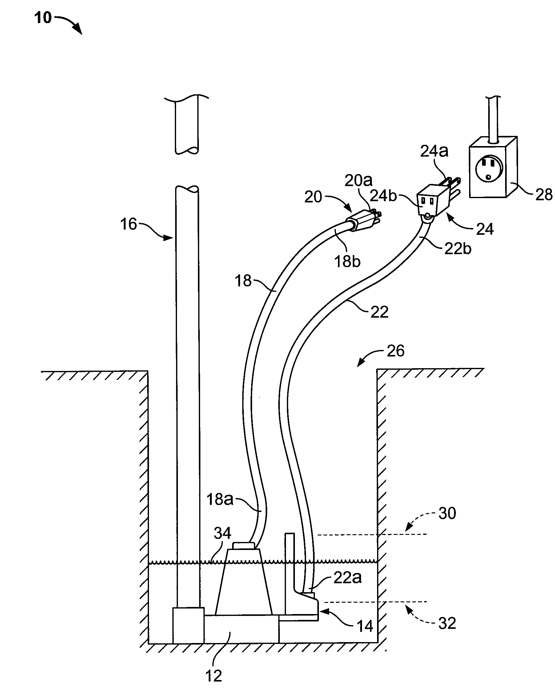
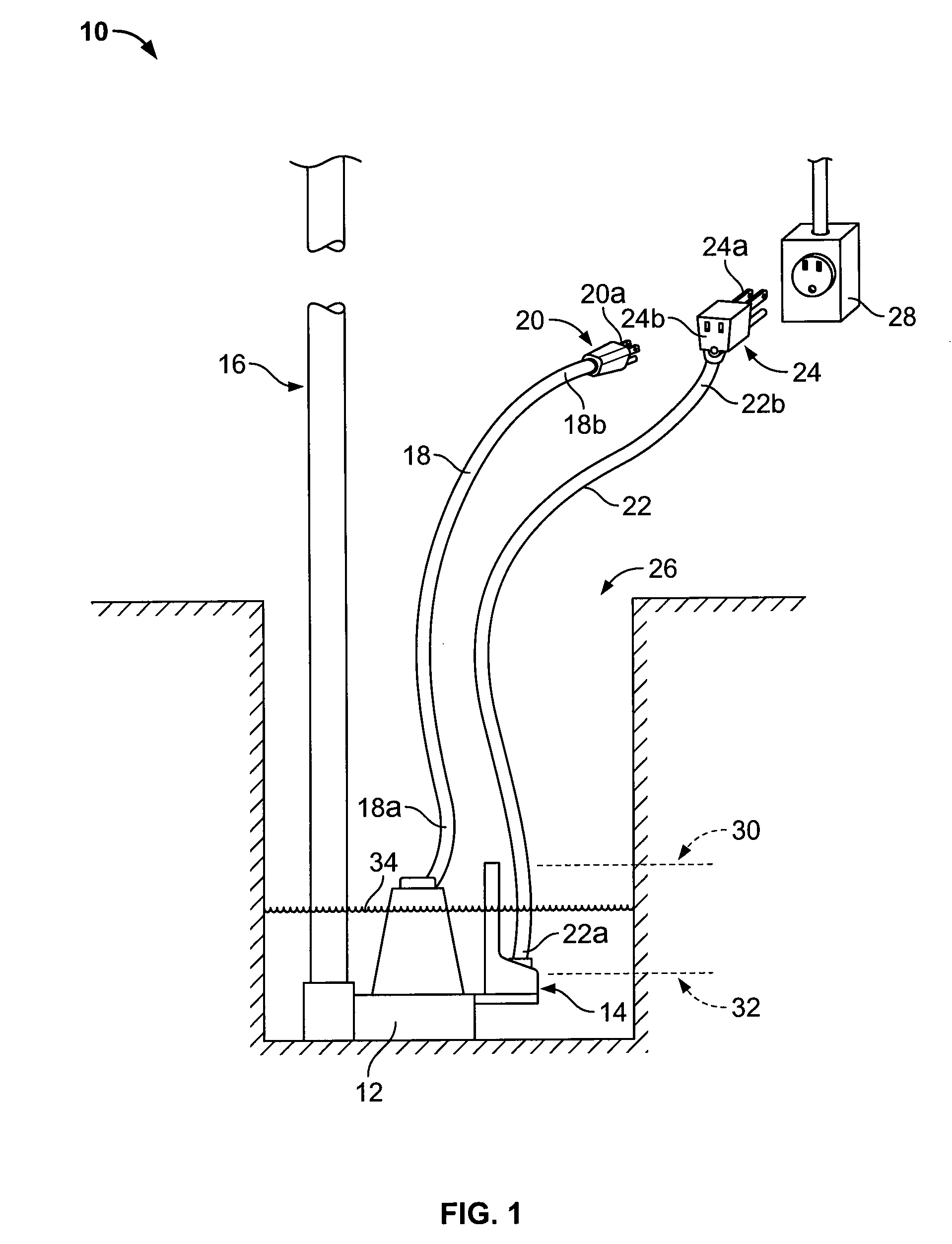
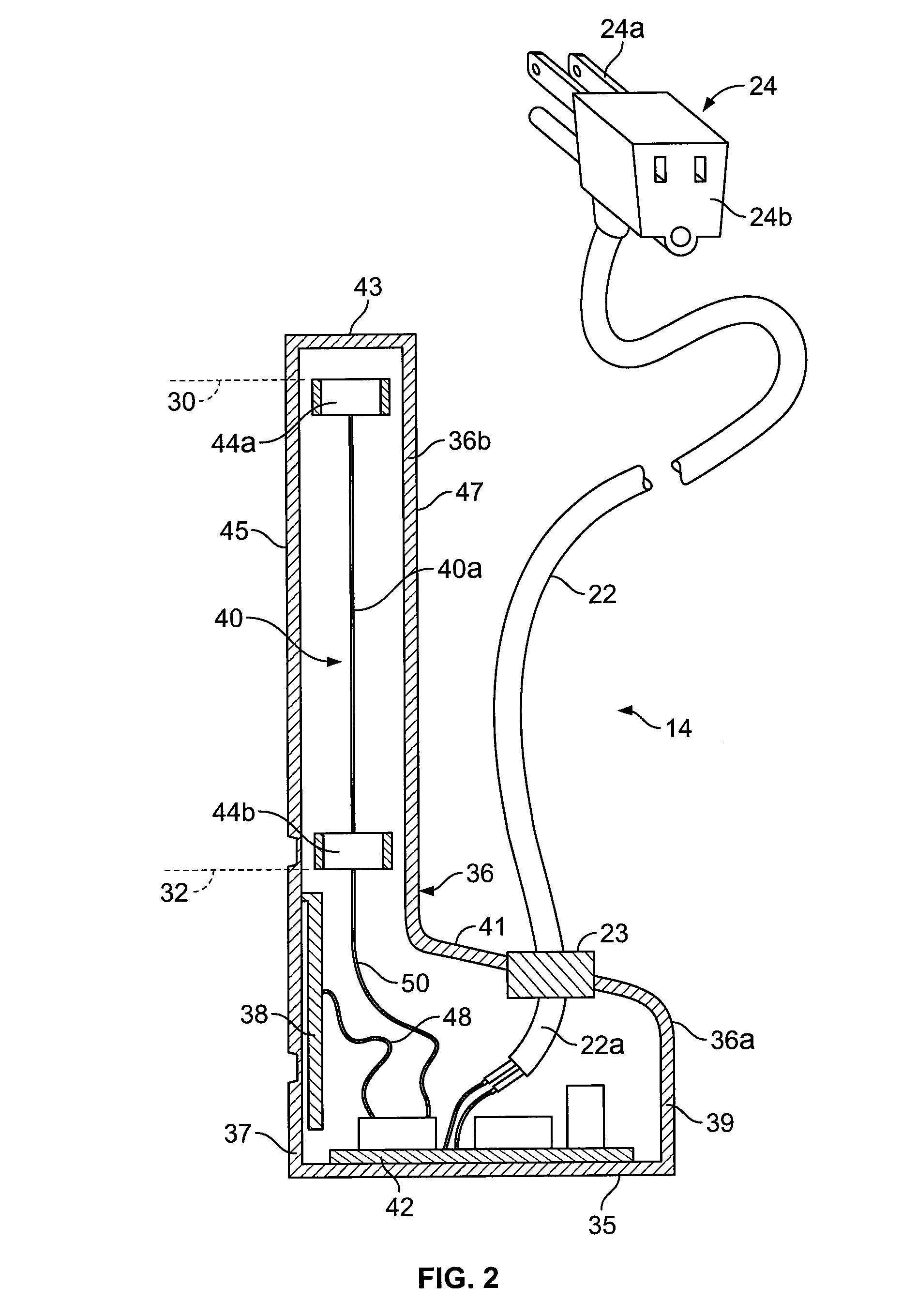
[0037]FIG. 1 depicts a sump pump system 10 disposed within a reservoir 26. The sump pump system 10 includes a pump 12, a sensor or sensor unit 14, and a discharge pipe 16. In general, the sensor unit 14 monitors the level of a liquid 34 within the reservoir 26 and serves as a switch for activating and deactivating the pump 12 based on that level. When the level of the liquid 34 reaches a predetermined upper limit, which is identified by reference numeral 30 in FIG. 1, the sensor unit 14 activates the pump 12. Upon activation, the pump 12 begins moving the liquid 34 up and out of the reservoir 26 via the discharge pipe 16. This begins to lower the level of the liquid 34 in the reservoir 26. Once the level of the liquid 34 reaches a predetermined lower limit, which is identified by reference numeral 32 in FIG. 1, the sensor unit 14 deactivates the pump 12. The details of the sump pump system 10 will now be discussed in more detail with continued reference to the figures.
[0038]FIG. 1 d...
PUM
| Property | Measurement | Unit |
|---|---|---|
| Time | aaaaa | aaaaa |
| Dielectric polarization enthalpy | aaaaa | aaaaa |
| Flow rate | aaaaa | aaaaa |
Abstract
Description
Claims
Application Information
 - R&D
- Intellectual Property
- Life Sciences
- Materials
- Tech Scout
- Unparalleled Data Quality
- Higher Quality Content
- 60% Fewer Hallucinations
Browse by: Latest US Patents, China's latest patents, Technical Efficacy Thesaurus, Application Domain, Technology Topic, Popular Technical Reports.
© 2025 PatSnap. All rights reserved.Legal|Privacy policy|Modern Slavery Act Transparency Statement|Sitemap|About US| Contact US: help@patsnap.com


