Robot having arm in which umbilical member is accomodated

a technology of umbilical member and arm, which is applied in the direction of mechanical control devices, process and machine control, instruments, etc., can solve the problems of unbalanced arm structure, difficult to maintain space, and difficult to properly and safely manage the robot, so as to reduce the influence of tool management inertia, reduce the gap, and remove the umbilical member smoothly

Inactive Publication Date: 2008-09-25
FANUC LTD
View PDF6 Cites 30 Cited by
  • Summary
  • Abstract
  • Description
  • Claims
  • Application Information

AI Technical Summary

Benefits of technology

[0008]In a robot having an arm structure in which an umbilical member is accommodated, such as the arc welding robot as set forth in JP-A-2003-200376, it is advantageous to reduce a gap defined between the tool managing and relaying unit and the arm structure as much as possible and dispose the tool managing and relaying unit in the neighborhood of a joint, in order to prevent interference between the tool managing and relaying unit and structures surrounding the robot, which may occur during movement of the arm, and reduce influence of inertia of the tool managing and relaying unit on the movement of the arm. On the other hand, the umbilical member laid or provided between the tool managing and relaying unit and the working tool at the distal end of the arm may be degraded or damaged due to bending or twisting caused during repeated arm movement, and therefore, it becomes necessary to periodically replace the umbilical member. Conventionally, when an umbilical member is replaced, the umbilical member is manually removed from the connection part of the tool managing and relaying unit. However, in a configuration where the gap between the tool managing and relaying unit and the arm structure is reduced as described above, it is difficult to maintain space between the tool managing and relaying unit and the arm structure sufficient to allow an operator to smoothly remove the umbilical member, and as a result, the umbilical member can not be replaced when necessar...

Problems solved by technology

On the other hand, the umbilical member laid or provided between the tool managing and relaying unit and the working tool at the distal end of the arm may be degraded or damaged due to bending or twisting caused during repeated arm movement, and therefore, it becomes necessary to periodically replace the umbilical member.
However, in a configuration where the gap between the tool managing and relaying unit and the arm structure is reduced as described above, it is difficult to maintain space between the tool managing and relaying unit and the arm structure sufficient to allow an ope...

Method used


Image

  • Robot having arm in which umbilical member is accomodated
  • Robot having arm in which umbilical member is accomodated
  • Robot having arm in which umbilical member is accomodated

Examples


Embodiment Construction

[0031]The embodiments of the present invention are described below, in detail, with reference to the accompanying drawings. In the drawings, same or similar components are denoted by common reference numerals.

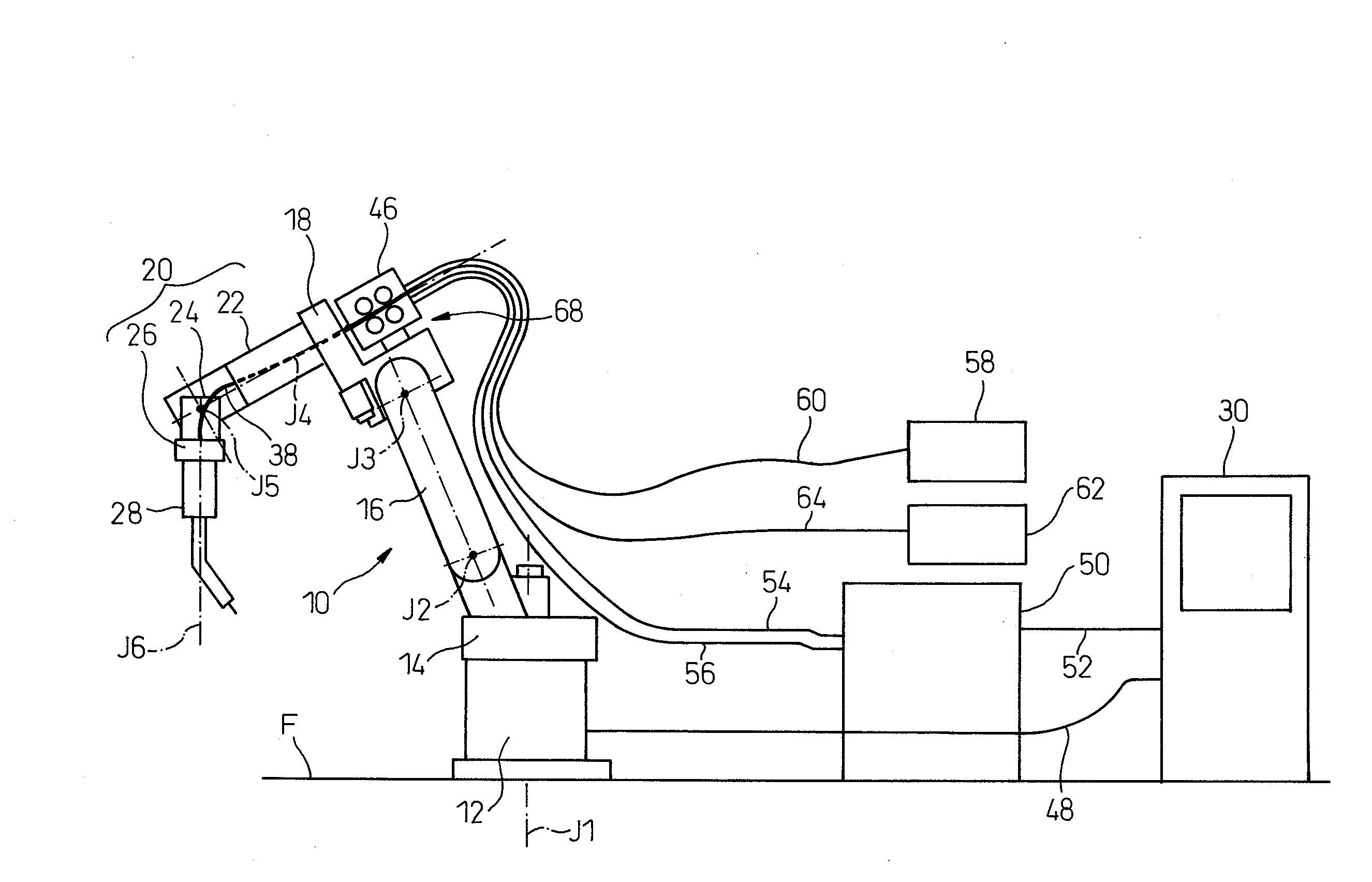
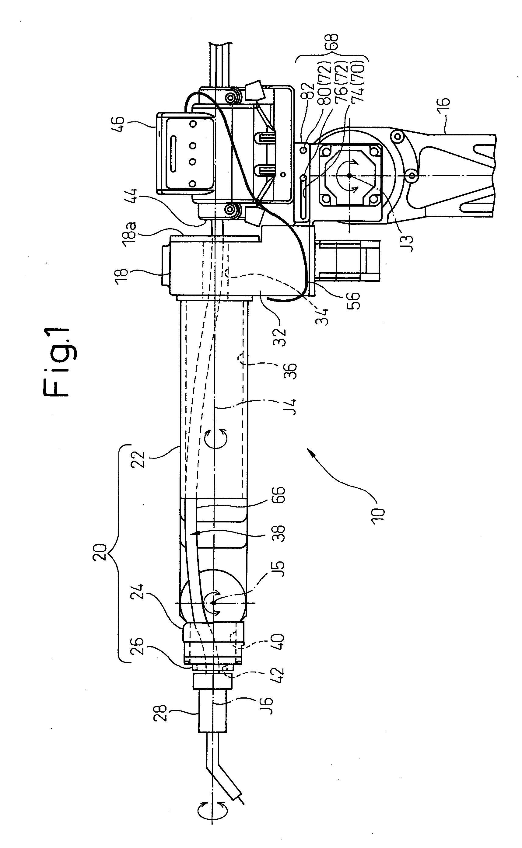
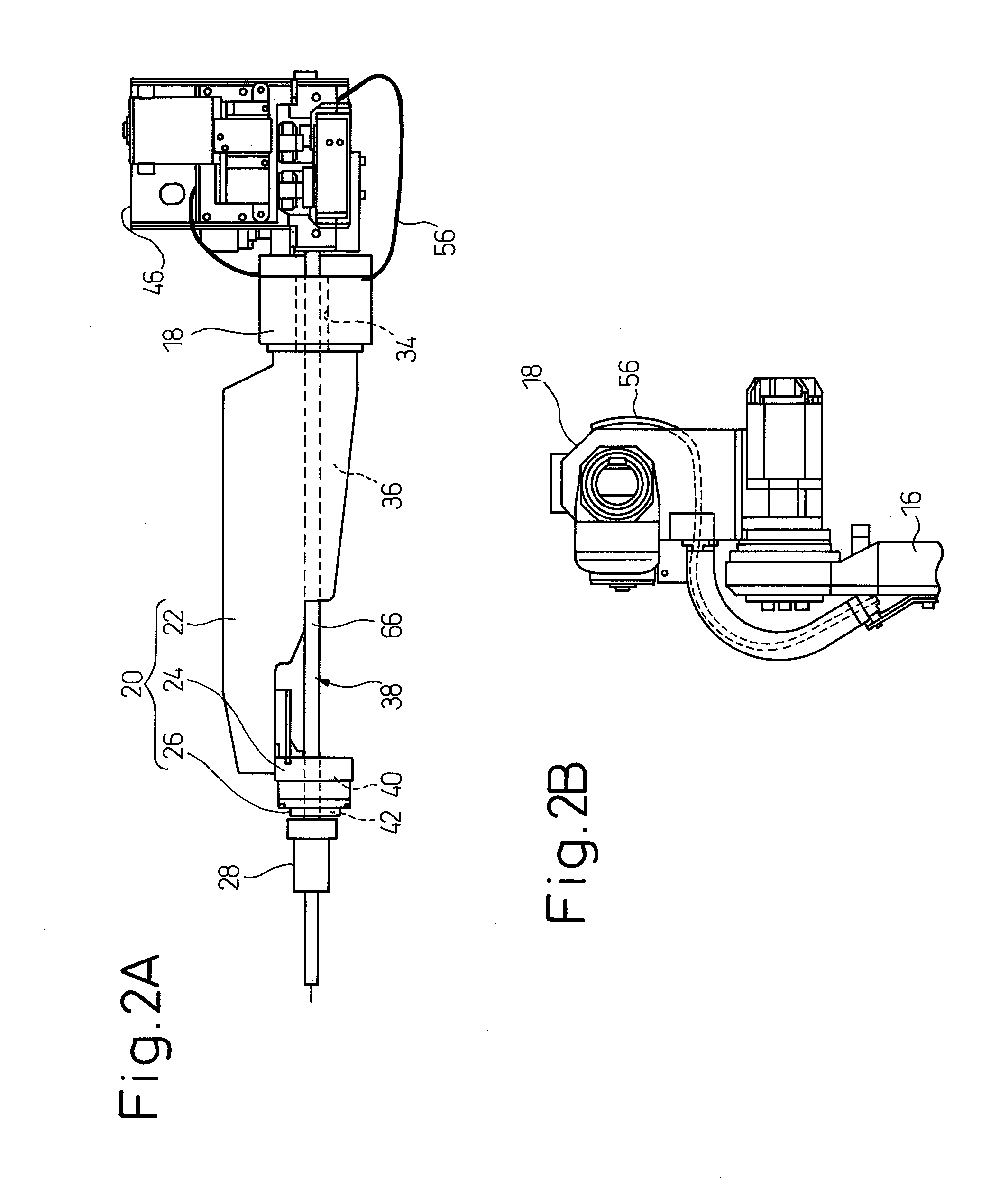
[0032]Referring to the drawings, FIGS. 1 to 2B show a major portion of a robot 10 according to an embodiment of the present invention. Further, FIG. 3 schematically shows an example of an entire configuration of a robot system including the robot 10. The illustrated robot 10 has a mechanical configuration of a 6-axis vertical articulated robot, but the robot according to the present invention is not limited to this mechanical configuration. In the present application, the term “robot” refers to a mechanical section excluding a controller.

[0033]The robot 10 includes an arm structure (i.e., a manipulator) having 6-degrees of freedom and supported on a stationary base 12 fixedly installed on a floor surface F (FIG. 3). The arm structure includes a rotary post 14 joined to the stat...


PUM


Abstract

A robot including a forearm section with a through passage, a wrist section articulated on the forearm section, and an umbilical member inserted through the through passage of the forearm section and provided along the wrist section. The robot includes a tool managing and relaying unit mounted on the forearm section close to the through passage and provided with a connection part to which the umbilical member is connected, and a mount mechanism carrying the tool managing and relaying unit movably between a first position where the connection part is disposed adjacent to an opening of the through passage and a second position where the connection part is spaced from the opening of the through passage, and releasably securing the tool managing and relaying unit to the forearm section at the first position.

Description

BACKGROUND OF THE INVENTION[0001]1. Field of the Invention[0002]The present invention relates a robot having an arm in which an umbilical member is accommodated.[0003]2. Description of the Related Art[0004]When an industrial robot (hereinafter simply referred to as a “robot”) performs processing work such as arc welding, laser processing, sealing, etc., or a handling work such as loading, unloading, bin picking, etc., it is required to supply energy such as electric power, laser beam, hydraulic fluid, etc., signals such as electrical signals, optical signals, etc., or a material such as wire, gas, sealant, etc., to a working tool (i.e., an end effector) such as a welding torch, a hand, etc., that is attached to a distal end of an arm structure (i.e., a manipulator) of the robot. The energy, signals, material, etc., are typically supplied by using a cable, a pipe, etc.[0005]For example, in an arc welding robot, a cable or pipe for supplying welding current, welding wire, assist gas, ...

Claims


Application Information

Patent Timeline
IPC IPC(8): B25J17/02
CPCY10T74/20305B25J19/0029
Inventor INOUE, TOSHIHIKONAKAYAMA, KAZUTAKAIWAYAMA, TAKATOSHIUEMURA, TOKITAKA
Owner FANUC LTD
Why Eureka
Try Eureka