Method of electric arc joining with alternating current

a technology of electric arc and alternating current, which is applied in the direction of arc welding apparatus, workpiece edge portions, and welding media, etc., can solve the problems described above, and achieve the effects of improving welding, high deposition rate, and broadening the possible applications

Inactive Publication Date: 2008-09-25
PANGAS
View PDF10 Cites 20 Cited by
  • Summary
  • Abstract
  • Description
  • Claims
  • Application Information

AI Technical Summary

Benefits of technology

The invention provides a method for joining materials using a fusible electrode and an alternating current. This method improves welding and expands the range of applications it can be used for. It also allows for higher deposition rates, reducing issues in both welding and soldering. Overall, this method solves problems in joining materials and makes them easier to join.

Problems solved by technology

The technical problem addressed in this patent is the improvement of arc joining, particularly in gas-shielded metal arc welding and resurface welding/soldering, by influencing the properties and position of the electric arc through the use of external magnetic fields. The problem of seam collapse, which occurs when a weld seam is formed, can also be addressed by controlling the mixing effect in resurface welding and soldering.

Method used


Image

  • Method of electric arc joining with alternating current
  • Method of electric arc joining with alternating current

Examples


Embodiment Construction

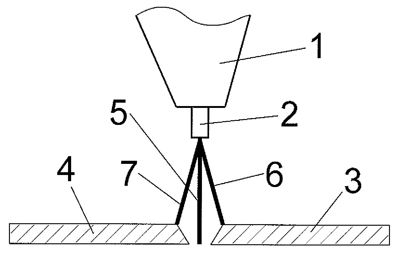
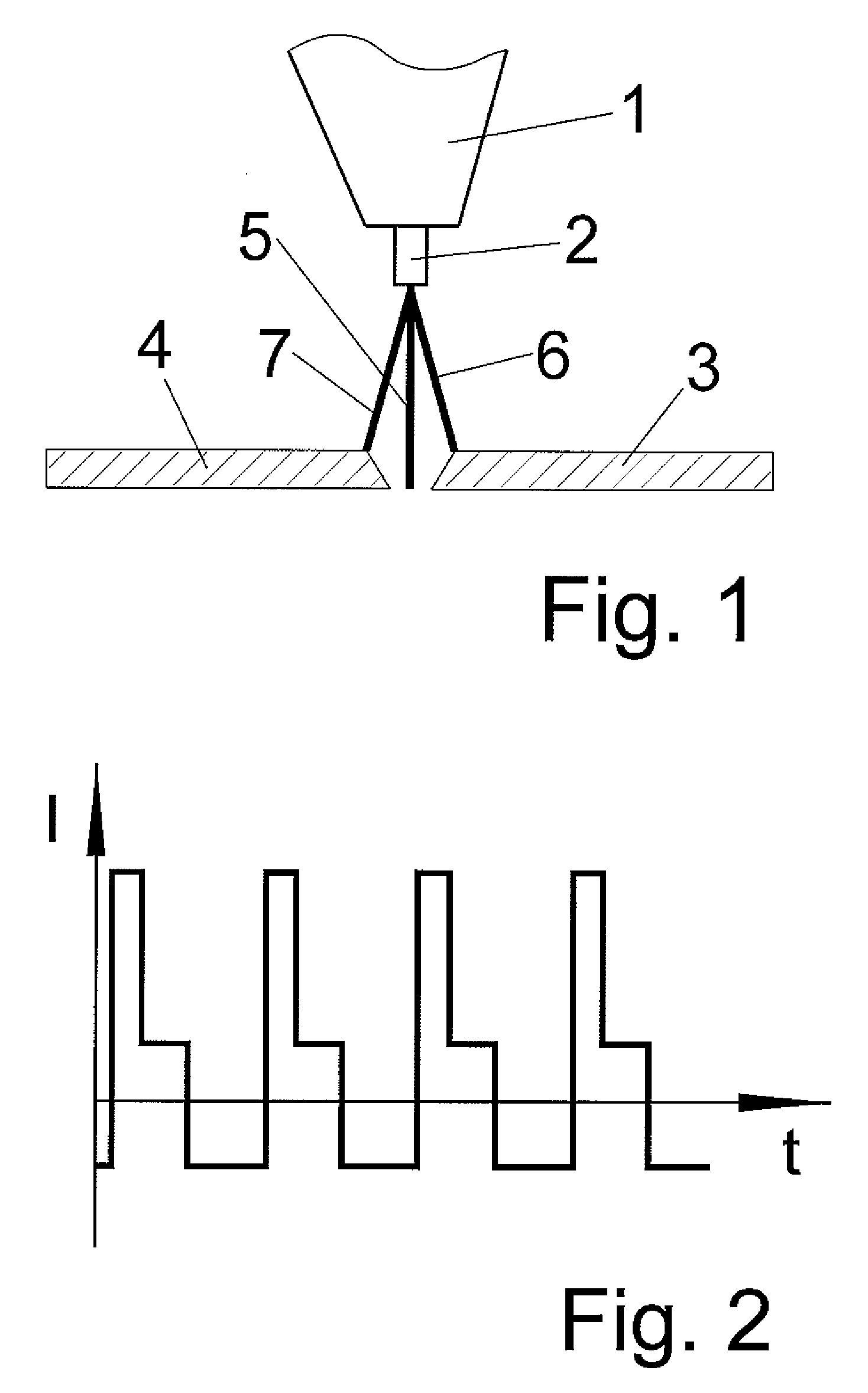
[0026]On the basis of FIGS. 1 and 2, the deflection of the arc in joining welding or joining soldering will now be explained in greater detail. The diagrams and dimensions in FIG. 1 are examples. FIG. 1 shows a welding torch 1 with a fusible electrode 2. Furthermore, FIG. 1 shows a workpiece in which a gap is to be bridged and a joint is to be created. The gap divides the workpiece into a right side 3 and a left side 4. Instead of the arc, FIG. 1 shows a schematic line situated at the center of the arc and thus showing the direction in which the arc burns. Without deflection, i.e., without applying an external magnetic field, the arc burns straight toward the workpiece. The direction of the arc thus follows line 5 here. According to the present invention, the arc is deflected out of the center of the molten weld pool to the right side 3 by an external magnetic field during a first positive pulsed current phase. The arc then burns in the direction of the right edge, i.e., in the flan...


PUM

PropertyMeasurementUnit
Material consumption rateaaaaaaaaaa
Magnetic fieldaaaaaaaaaa

Abstract

The invention relates to a method for arc joining, in particular for arc welding, such that an arc burns between a workpiece and a fusible electrode at a processing site such that an alternating current with at least one positive alternating current phase and at least one negative alternating current phase is applied between the electrode and the workpiece such that the positive alternating current phase is divided into at least one positive pulsed current phase and at least one positive basic current phase and such that the arc is influenced at least temporarily by at least one external magnetic field. According to this invention, the arc is deflected at least temporarily out of the center of the processing site by one or more external magnetic fields during the positive pulsed current phase such that the arc is deflected into a first direction during a positive pulsed current phase and into a second direction which differs from the first direction during the next positive pulsed current phase.

Description


Claims


Application Information

Patent Timeline
Owner PANGAS
Why Eureka
Try Eureka