Precompression system for a liquid dispensing device and method of assembling such precompressed system

a liquid dispenser and pre-compression technology, which is applied in the direction of liquid transfer devices, single-unit devices, instruments, etc., can solve the problems of irregular dispensing pressure, large number of separate parts, and insufficient atomization of liquid, so as to achieve short and sturdy, less prone to deformation

Active Publication Date: 2008-09-25
DISPENSING TECH
View PDF6 Cites 40 Cited by
  • Summary
  • Abstract
  • Description
  • Claims
  • Application Information

AI Technical Summary

Benefits of technology

[0010]In accordance with a first aspect of the present invention, a precompression system for a liquid dispensing device that has an inlet and an outlet comprises a pump chamber and a valve chamber. The pump chamber includes a piston that is movable in the pump chamber for drawing liquid through the inlet and discharging the liquid through the outlet. The valve chamber includes a valve member that is disposed between the pump chamber and the outlet and that is operable to allow liquid in the pump chamber to reach the outlet only after a predetermined pressure is established in said pump chamber and to stop liquid from reaching the outlet when the pressure in the pump chamber falls below said predetermined pressure. The valve chamber has an inlet end in fluid communication with said pump chamber, an outlet end in fluid communication with the outlet and a valve seat that is arranged between the inlet end and the outlet end and that has an opening extending therethrough. The valve member comprises an elastic diaphragm that normally closes the valve seat opening and that includes a concave surface facing the valve seat opening and in fluid communication with the pump chamber and a convex surface in fluid communication with atmospheric pressure. By arranging the elastic diaphragm such that its concave surface faces and engages the valve seat, the pressure at which the precompression valve opens may be controlled more accurately. This is due to the fact that the valve is opened by stretching of the elastic diaphragm, rather than flexing. Moreover, this configuration of the valve member avoids any risk of inversion of the diaphragm.
[0011]In a preferred embodiment, the elastic diaphragm is stretched around the valve seat. By stretching the diaphragm it is prestressed, which results in improved sealing and better control of the opening pressure.
[0012]In a further preferred embodiment the elastic diaphragm has an outer periphery and the valve member includes a sleeve surrounding and holding the outer periphery of the diaphragm and extending substantially perpendicular to the plane of the diaphragm, the sleeve being sealingly arranged in the valve chamber. In this way the elastic diaphragm may be easily mounted in the valve chamber.
[0015]In order to ensure that deformation of the valve member will be limited to the elastic diaphragm only, the sleeve preferably includes a plurality of ribs extending along an inner wall thereof substantially perpendicular to the plane of the diaphragm. In this way movement of the diaphragm is well defined, while the sleeve will continue to seal the valve chamber.
[0016]In a further preferred embodiment of the precompression system of the invention, the sleeve has a lengthwise dimension substantially perpendicular to the plane of the diaphragm and a diametral dimension substantially parallel to the plane of the diaphragm, wherein the lengthwise dimension is greater than a corresponding dimension of the valve chamber. This ensures that the sleeve is clamped tightly in the valve chamber when the precompression system is assembled.
[0017]Where the sleeve has a lengthwise dimension substantially perpendicular to the plane of the diaphragm and a diametral dimension substantially parallel to the plane of the diaphragm, this diametral dimension may further advantageously be greater than the lengthwise dimension. This results in a relatively short and sturdy sleeve, which is less prone to deformation when the valve member is subjected to the pressure generated by the pump.

Problems solved by technology

The precompression system of this prior art trigger sprayer serves to prevent liquid from leaving the outlet at too low a pressure, which would result in insufficient atomization of the liquid with large drops of fluid or liquid being formed in the spray pattern.
Among the problems associated with this prior art liquid dispenser and its precompression system are the large number of separate parts, which moreover are made from different materials, and the sometimes irregular dispensing pressures achieved by the precompression system.
The high number of parts results in a product that is both difficult to manufacture and assemble.
As a result, both the manufacturing and the assembly of the dispenser parts are expensive and time consuming.
In addition, the different materials pose problems in handling and recycling the trigger sprayer and the container when the items are ready to be discarded.
This is an unstable situation, which may lead to the same amount of pump pressure resulting in varying deformation and consequently varying degrees of opening of the spring valve.
Moreover, there is a risk that the spring valve may abruptly snap to an inverted position, thus leaving an open connection between the pump and the outlet.

Method used


Image

  • Precompression system for a liquid dispensing device and method of assembling such precompressed system
  • Precompression system for a liquid dispensing device and method of assembling such precompressed system
  • Precompression system for a liquid dispensing device and method of assembling such precompressed system

Examples


first embodiment

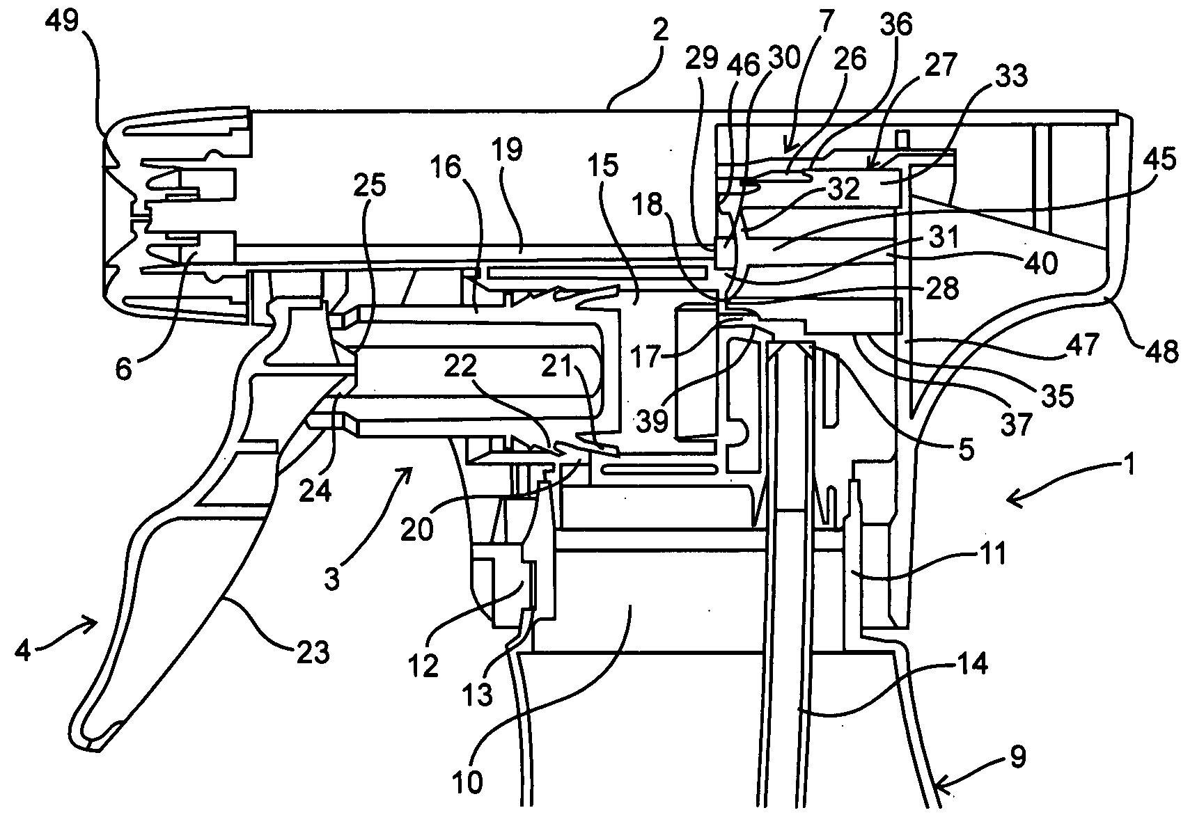
[0037]FIG. 1 shows a fragmentary longitudinal sectional view of a liquid dispenser 1 in accordance with the present invention. The liquid dispenser 1 comprises a housing 2, a pump 3, an operating mechanism 4, an inlet 5, an outlet 6 and a precompression system 7. A discharge nozzle 49 is arranged on the outlet 6 for atomizing the liquid that is dispensed. The liquid dispenser 1 is connected to a container 9 having an opening 10 bordered by a neck 11. In the illustrated embodiment this connection is a snap connection, which is effected by snapping lugs 12 arranged on an inner surface of the housing 2 into recesses 13 formed in the outer surface of the neck 11. A dip tube 14 extends from the inlet 5 of the liquid dispenser 1 into the container 9 for drawing liquid from the container 9 into the liquid dispenser 1.

[0038]The pump 3 includes a pump chamber 15 and a piston 16 that is arranged in the pump chamber 15 for reciprocating movement. Pump chamber 15 has an inlet opening 17 communi...

third embodiment

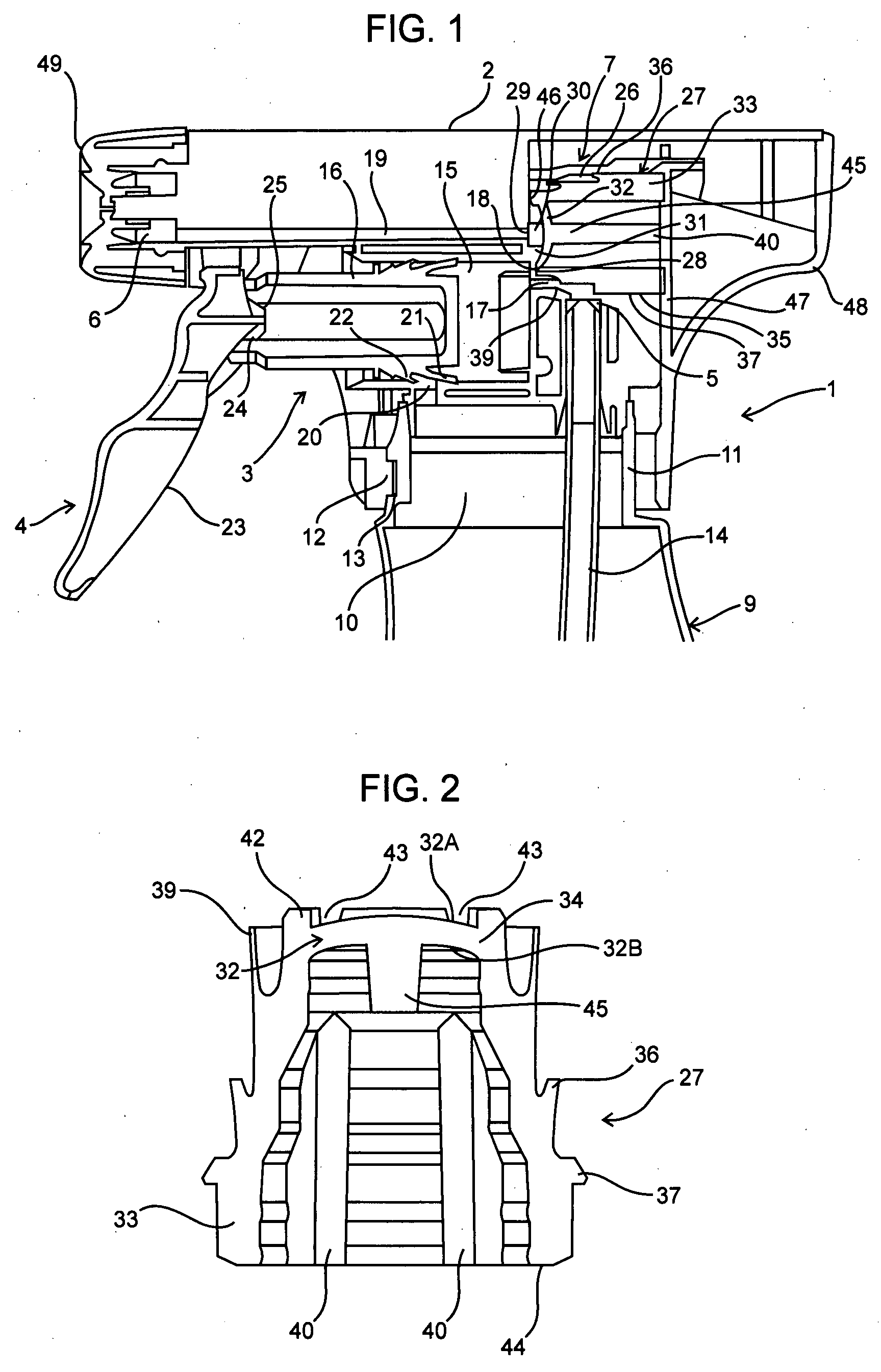
[0052]The valve member 227 of this third embodiment is somewhat different from that of the first two embodiments in that the elastic diaphragm 232 is arranged substantially halfway the sleeve 233, rather than near its inner ridge 242. Like in the first two embodiments, the diaphragm 232 is stretched over the valve seat 231, as shown in FIG. 13. Its concave side 232A again faces both the valve opening 230 and the outlet opening 218 of the pump chamber 215 and is exposed to the pressure generated by the pump 203. The convex side 232B of the elastic diaphragm 232 faces the rear of the valve chamber 226 and is exposed to atmospheric pressure.

[0053]Again, the elastic diaphragm 232 is originally molded in a shape that is substantially less concave than the shape it has to assume by being stretched over the valve seat 231 when valve member 227 is inserted into valve chamber 226. This deformation of the elastic diaphragm 232 leads to a certain degree of prestress that results in an excellen...


PUM


Abstract

The invention relates to a precompression system for a liquid dispensing device, which prevents liquid from being discharged until a predetermined pressure has been built up. The precompression system comprises a pump for drawing liquid through an inlet and discharging it through an outlet and a precompression valve disposed between the pump and the outlet. The precompression valve allows liquid in the pump to reach the outlet only after the predetermined pressure is established and stops liquid from reaching the outlet when the pressure falls below the predetermined level. The precompression valve comprises an elastic diaphragm normally closing the valve opening and including a concave surface facing the valve opening and in fluid communication with the pump and a convex surface in fluid communication with atmospheric pressure. The elastic diaphragm may be stretched around a valve seat.The invention further relates to a method of assembling such a precompression system in a liquid dispensing device.

Description

FIELD OF THE INVENTION[0001]The present invention relates to liquid dispensers and more specifically relates to a precompression system for a liquid dispenser whereby liquid in a container is not discharged from the dispenser until a predetermined pressure level is reached. The invention also relates to a method of assembling such a recompression system in a liquid dispenser.BACKGROUND OF THE INVENTION[0002]Containers having liquid dispenser assemblies secured thereto are well known. U.S. Pat. No. 5,730,335 discloses a liquid dispenser including a precompression system. This liquid dispenser is a trigger sprayer having a sprayer housing that may be fixed onto the neck of a container. The sprayer housing contains a manually operated pump. An operating element in the shape of a trigger is pivotally connected to the housing for operating the pump. A dip tube may extend from the pump and into the container so that the liquid in the container may be drawn through the dip tube and into th...

Claims


Application Information

Patent Timeline
Patent Type & Authority Applications(United States)
IPC IPC(8): B05B11/00
CPCB05B11/0062B05B11/3011B05B11/3069B05B11/3064B05B11/3045Y10T137/7879B05B11/0008B05B11/1011B05B11/1064B05B11/1069B05B11/00B05B11/02B05B11/1045
Inventor MAAS, WILHELMUS JOHANNES JOSEPHWILHELMUS HURKMANS, PETRUS LAMBERTUS
Owner DISPENSING TECH
Why Eureka
Try Eureka