
Method for Manufacturing a Workpiece by Friction Welding to Reduce the Occurrence of Abnormal Grain Growth

Inactive Publication Date: 2008-09-25
THE BOEING CO
View PDF26 Cites 22 Cited by
  • Summary
  • Abstract
  • Description
  • Claims
  • Application Information

AI Technical Summary

Benefits of technology

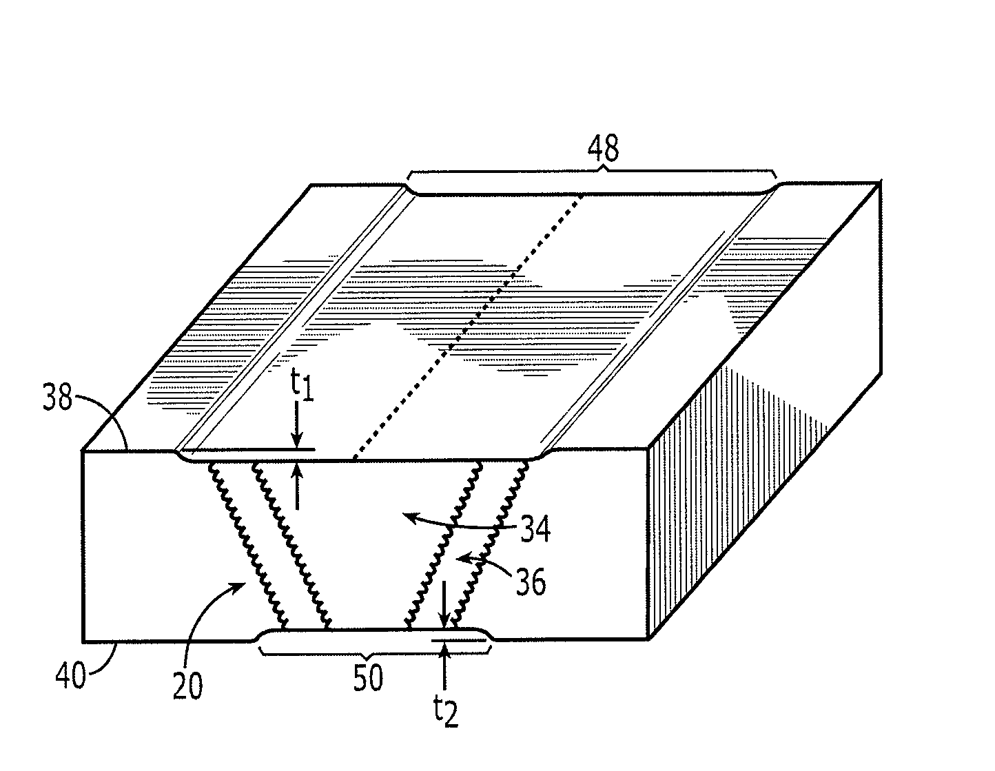
[0007]Embodiments of the present invention provide methods of manufacturing a workpiece by friction stir welding and an associated workpiece, in which material is selectively removed from the surfaces of the workpiece at the location of a friction stir weld joint to at least partially prevent grain growth during a subsequent thermal treatment.
[0010]According to one embodiment, the method further includes, prior to selectively removing the material, determining a minimum thickness of the material to be selectively removed from each of the first and second surfaces of the workpiece in the removing operation to thereby substantially prevent a nonuniform grain growth during the solution treat, quench, and age treatment. For example, two or more test members can be provided, each test member defining a friction stir weld joint, and different thicknesses of material can be removed from surfaces of the test members at locations of the friction stir weld joints, before subjecting the test members to thermal treatments and then testing the test members to determine the minimum thickness of the material to be selectively removed.

Problems solved by technology

However, in some cases the friction welding operation leads to a change in the material properties proximate the weld joint.
In particular, the friction stir welding process can result in changes in the material, and these material changes can affect the performance of the material in use or during subsequent processing operations.
For example, in a typical operation of friction stir welding high strength aluminum alloys, such as 7000 series alloys, the heat associated with friction stir welding typically results in coarsening of precipitates in a heat affected zone near the friction stir welding joint, thereby decreasing the strength of the material in the heat affected zone.
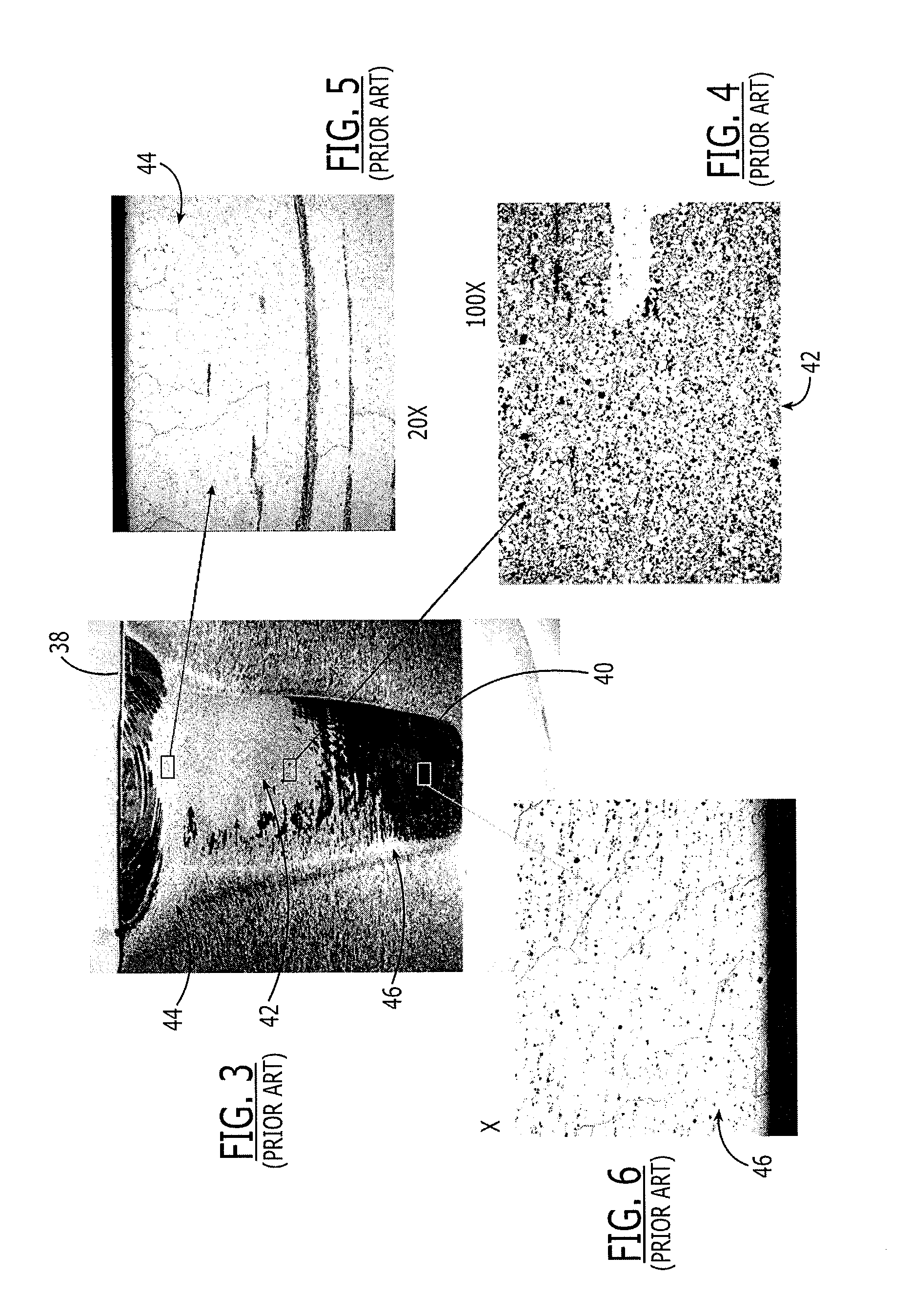
Although such a heat treatment process can be effective for improving the properties of the material in the heat affected zone, the heat treatment can also nucleate abnormal grain growth in the nugget portion of the weld joint.
That is, the grain size of the material in the weld joint can grow nonuniformly and undesirably during the heat treatment.
The use of relatively low-temperature post-weld aging instead of conventional thermal heat treatments has not been found to effectively achieve high strengths at the weld joints.

Method used


Image

  • Method for Manufacturing a Workpiece by Friction Welding to Reduce the Occurrence of Abnormal Grain Growth
  • Method for Manufacturing a Workpiece by Friction Welding to Reduce the Occurrence of Abnormal Grain Growth
  • Method for Manufacturing a Workpiece by Friction Welding to Reduce the Occurrence of Abnormal Grain Growth

Examples


Embodiment Construction

[0023]The present invention now will be described more fully hereinafter with reference to the accompanying drawings, in which preferred embodiments of the invention are shown. This invention may, however, be embodied in many different forms and should not be construed as limited to the embodiments set forth herein; rather, these embodiments are provided so that this disclosure will be thorough and complete, and will fully convey the scope of the invention to those skilled in the art. Like numbers refer to like elements throughout.

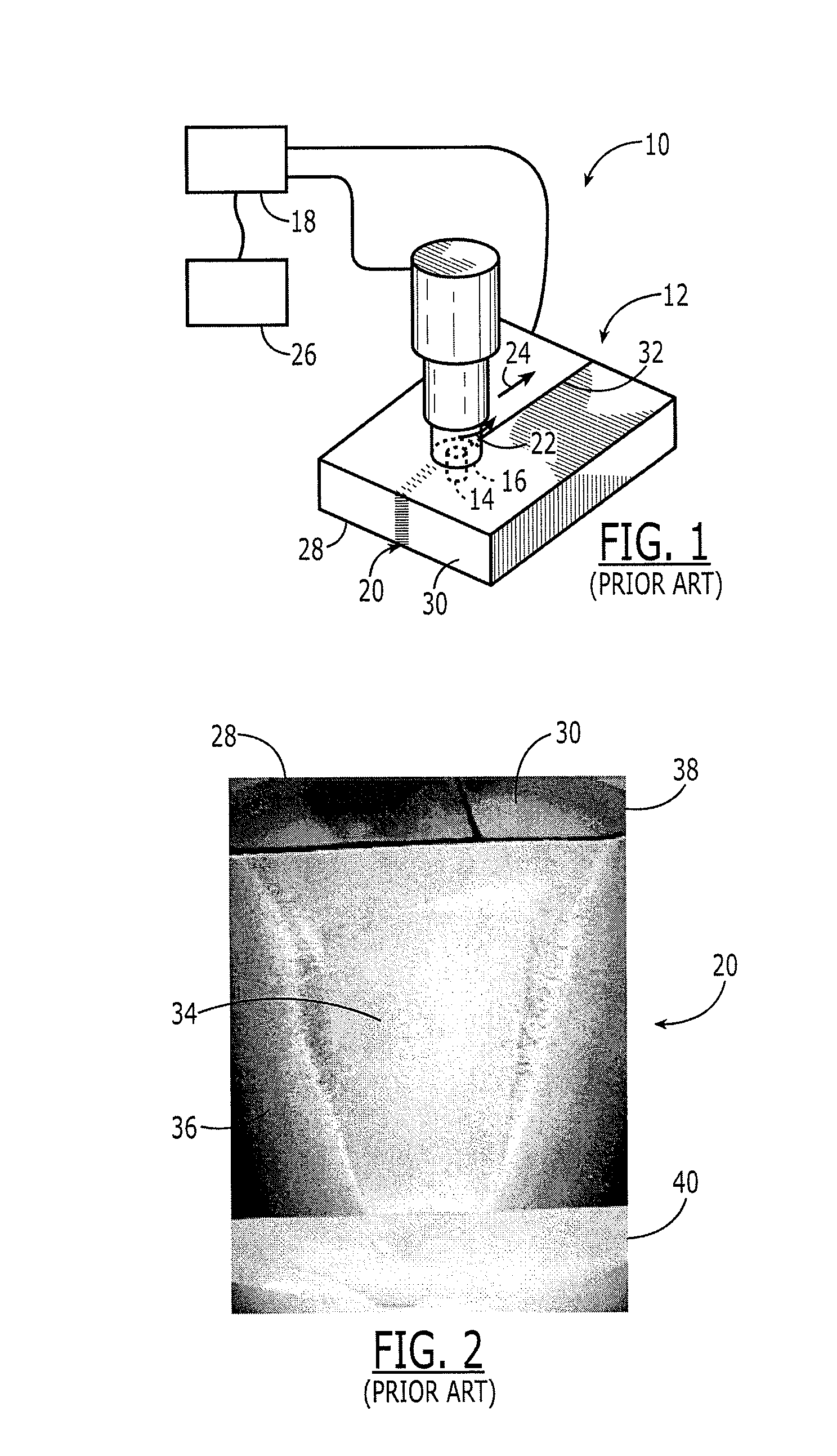
[0024]Referring now to the drawings and, in particular, to FIG. 1, there is shown a conventional friction stir welding apparatus 10 for friction stir welding a workpiece 12. The friction stir welding apparatus 10 includes a friction stir welding tool having a pin 14 that extends from a shoulder 16, and at least one actuator 18 for rotating the tool and moving the tool through the workpiece 12 to form a friction weld joint 20. For example, the friction stir...


PUM

PropertyMeasurementUnit
Grain sizeaaaaaaaaaa
Thicknessaaaaaaaaaa
Thicknessaaaaaaaaaa

Abstract

A method of manufacturing a workpiece is provided. The method generally includes friction stir welding at least one structural member, selectively removing material from the surfaces of the workpiece at the location of a friction stir weld joint, and thereafter subjecting the workpiece to a solution treat, quench, and age treatment. By selectively removing regions from the surfaces of the workpiece that are defined by nonuniform material properties adapted to nucleate nonuniform grain growth during the solution treat, quench, and age treatment, a subsequent grain growth during the thermal treatment can be at least partially prevented.

Description

BACKGROUND OF THE INVENTION[0001]1) Field of the Invention[0002]Embodiments of this invention relate to the manufacture of a workpiece and, more specifically, to a method of manufacture in which a workpiece is friction welded and the occurrence of abnormal grain growth in the workpiece during a heat treatment operation is reduced or prevented.[0003]2) Description of Related Art[0004]Friction stir welding is a process in which a rotating tool, such as a pin or probe, is urged into and / or through a workpiece, e.g., to join multiple structural members of the workpiece in a solid state or to repair cracks or other defects in a workpiece. According to one conventional friction stir welding process, two structural members are disposed in an abutting or overlapping configuration to define an interface therebetween. A shoulder of the tool that can be flat, concave, or otherwise contoured is urged against one side of the structural members so that a pin of the tool that extends from a should...

Claims


Application Information

Patent Timeline
IPC IPC(8): B23K20/12
CPCC22F1/04B23K20/1225B23K20/12
Inventor LEDERICH, RICHARD J.BAUMANN, JOHN A.
Owner THE BOEING CO
Learn More