Method for determining noise floor level and radar using the same

a noise floor and radar technology, applied in the direction of using reradiation, measuring devices, instruments, etc., can solve the problems of interference between the fmcw radar with which the subject vehicle is equipped and the other radar installed in the other vehicle, and the range measurement obtained from a two-frequency cw radar in the presence of multiple target objects is unreliable, so as to achieve accurate detection of the noise floor level of the frequency spectrum characteristic

Active Publication Date: 2008-09-25
DENSO CORP
View PDF28 Cites 31 Cited by
  • Summary
  • Abstract
  • Description
  • Claims
  • Application Information

AI Technical Summary

Benefits of technology

[0022]The present invention has been made to solve the above-mentioned problems, and therefore an object of the present invention is to provide an FMCW radar, in particular a vehicle-mounted FMCW radar, and a method for accurately detecting noise floor level of the frequency spectrum characteristic of a beat signal which is obtained by mixing a transmission signal modulating a radar wave so as to linearly vary with time and a received signal relating to a reflected radar wave from a target object, based on a histogram illustrating distribution of the intensities of the frequency components of the beat signal, in order to accurately determine whether interference between the FMCW radar and some other radar occurs even if some large or long target object such as trucks and lorries, or large and long buildings such as a freeway and its piers is at place beyond the measuring region of the FMCW radar.

Problems solved by technology

Unfortunately, the two-frequency CW radar performs poorly when there are multiple target objects at different ranges, and thus the range measurement obtained from a two-frequency CW radar in the presence of multiple target objects unreliable.
That is, interference between the FMCW radar with which the subject vehicle is equipped and the other radar installed in the other vehicle may occur.
As a result of interference, it is hard to detect the beat frequencies accurately, and the distance to the target object such as the preceding vehicle or the relative speed of the target object cannot be accurately detected.
One of the reasons for difficulties in detecting such target characteristic accurately is that frequency spectrum characteristic of the beat signal contains a broad peak.
As a result, the peak frequency cannot be detected accurately for the beat frequency.
This results in an inaccurate detection of the target characteristic.
That is, the distance to the target object or the relative speed of the target object may be erroneously determined.
Hence, the conventional FMCW radars using the above mentioned fact may erroneously detect interference due to the existence of large or long target objects located far beyond the measuring region of the FMCW radar.
Thus, large target objects located far beyond the measuring region of the FMCW radar enhance the sum of intensities of the high frequency components and increase the number of frequency components which satisfy the predetermined conditions even if there are no other radars near, and result in erroneous determination of occurrence of interference between the FMCW radar and some other radar.
The above-mentioned difficulties pose a problem: how the noise floor level should be estimated accurately based on incident wave to the receiving antennas of the radar.
This determination may be a difficult task if any interference between the radar and some other radar occurs.
However, it is necessary to suspend the transmit operation to estimate the noise floor level and to detect occurrence of interference.
This means that during noise floor level estimation and interference detection, any target characteristic such as presence of a target object within the measuring range of the radar system, distance between the radar system and the target object, and relative velocity of the target object to the radar system can not be determined.
This means that a continuous measurement of target characteristic can not performed.

Method used


Image

  • Method for determining noise floor level and radar using the same
  • Method for determining noise floor level and radar using the same
  • Method for determining noise floor level and radar using the same

Examples


Embodiment Construction

[0056]Preferred embodiments of the present invention will be explained below with reference to attached drawings. Identical constituents are denoted by the same reference numerals throughout the drawings.

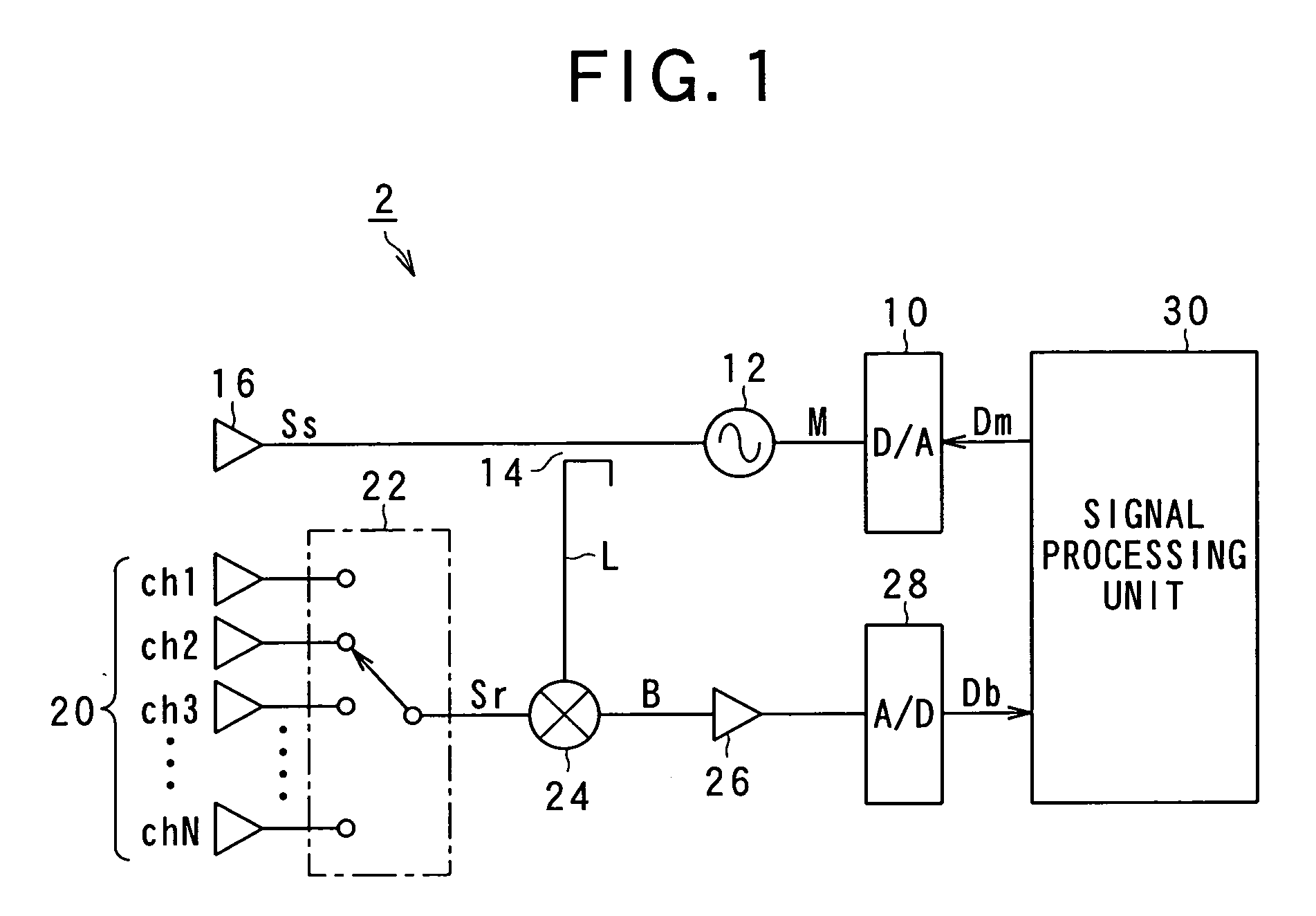
[0057]FIG. 1 is a block diagram showing a vehicle-mounted FMCW radar according to the present invention. The FMCW radar detects the distance to a target object located in a measuring range and / or a relative speed of the target object such as a preceding vehicle.

[0058]As shown in FIG. 1, the FMCW radar 2 includes a digital-analog (D / A) converter 10, an oscillator 12, a splitter 14, a transmitting antenna 16, and a signal processing unit 30.

[0059]The D / A converter 10 receives digital data Dm from the signal processing unit 30 and converts the received digital data Dm to an analog signal M. The oscillator 12 receives the analog signal M from the D / A converter 10 and thereby generates a radio frequency signal in the millimeter wave band, the frequency of the signal varying in time accor...


PUM


Abstract

A method for a radar for detecting a noise floor level of an electric signal corresponding to an incident radio wave received by the radar, the incident radio wave including a return of a radar wave that is transmitted from the radar toward a measuring range of the radar to detect target object characteristic including presence of a target object within the measuring range of the radar, a distance between the target object and the radar, and a relative speed of the target object to the radar is provided. The method includes steps of: calculating a histogram of intensities of frequency components, the frequency components exceeding a predetermined value relating to the measuring range, and extracting an intensity having the maximum height in the histogram as the noise floor level of the electric signal.

Description

CROSS REFERENCE TO RELATED APPLICATION[0001]The present application relates to and incorporates by reference Japanese Patent Applications 2007-72894 filed on Mar. 20, 2007.BACKGROUND OF THE INVENTION[0002]1. The Field of the Invention[0003]The present invention relates to a method for a radar for determining a noise floor level that is increased in response to interference by a radar wave transmitted from some other radar. The present invention further relates to an interference detecting device for a frequency modulated continuous wave (FMCW) radar and the FMCW radar equipped with interference detecting device using the method for estimating the noise floor level to accurately determine occurrence of interference between the FMCW radar and some other radar.[0004]2. Description of the Prior Art[0005]A number of automotive radar systems which are suited to vehicle safety system, for example, crash protection systems that minimize the effects of an accident, reversing warning systems ...

Claims


Application Information

Patent Timeline
Patent Type & Authority Applications(United States)
IPC IPC(8): G01S13/58
CPCG01S7/354G01S2007/356G01S13/345G01S7/356
Inventor SAKAMOTO, MAI
Owner DENSO CORP
Why Eureka
Try Eureka