Video Processing Apparatus and Video Display Apparatus

a technology of video display and video processing apparatus, which is applied in the direction of television systems, instruments, color signal processing circuits, etc., can solve the problems of image breakdown in display, difficulty in obtaining precise motion vectors, etc., and achieves the effects of preventing image breakdown, reducing frame rate, and reducing frame ra

Active Publication Date: 2008-09-25
MAXELL HLDG LTD
View PDF11 Cites 48 Cited by
  • Summary
  • Abstract
  • Description
  • Claims
  • Application Information

AI Technical Summary

Benefits of technology

[0007]According to such constitutions, as a result of processing for frame rate conversion using the motion compensation method, an adaptive interpolation control can be effected by detecting features in images so that the qualities of the resultant animations can ...

Problems solved by technology

However, such conventional motion compensation processes makes it difficult to obtain precise motion vectors in the case where plural...

Method used


Image

  • Video Processing Apparatus and Video Display Apparatus
  • Video Processing Apparatus and Video Display Apparatus
  • Video Processing Apparatus and Video Display Apparatus

Examples


embodiment 1

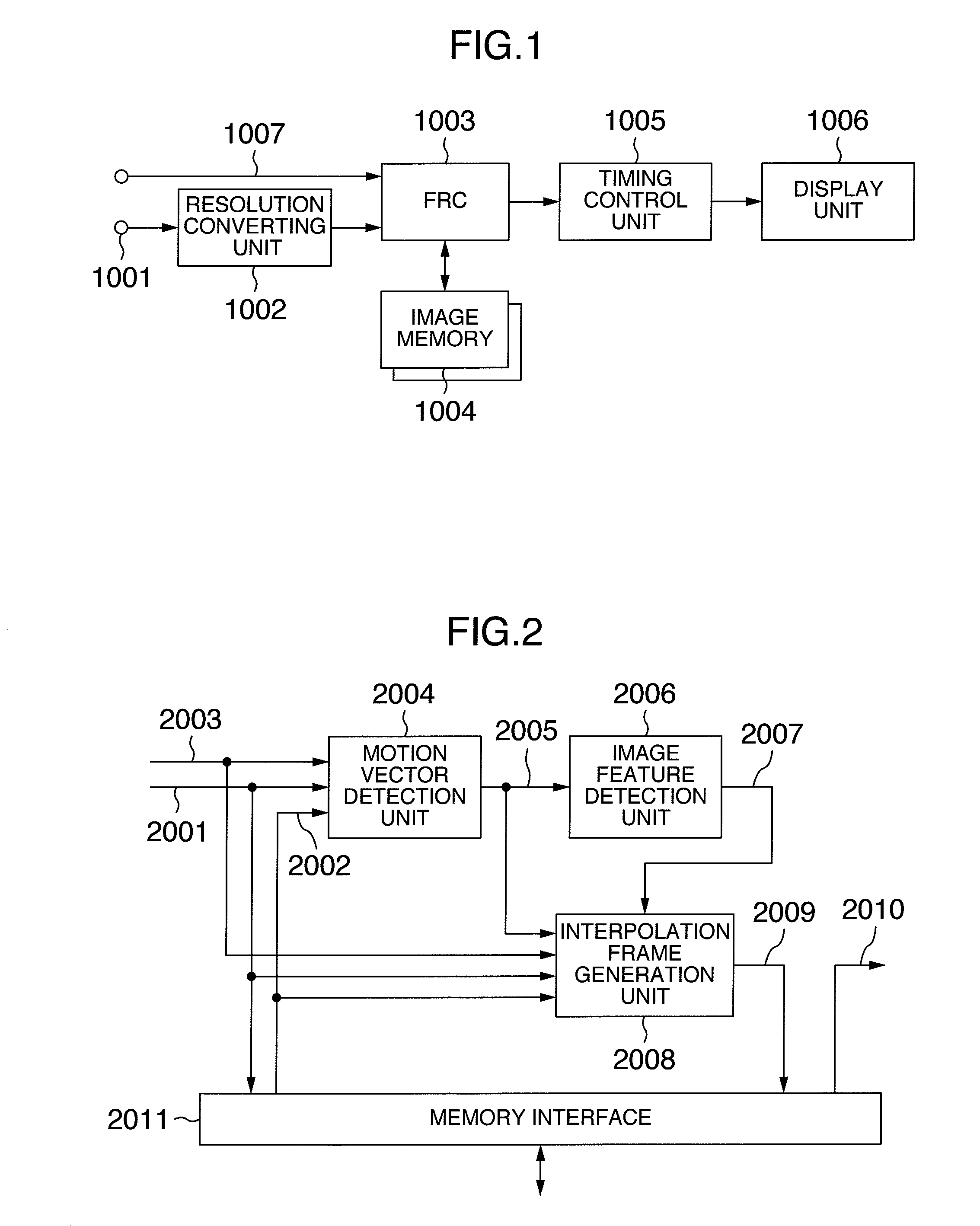
[0035]FIG. 1 is a block diagram of a video processing apparatus as a first embodiment of this invention. In FIG. 1 are shown an input signal 1001, a resolution converting unit 1002, a frame rate conversion (hereafter referred to as FRC for short) unit 1003, an image memory 1004, a timing control unit 1005, a display unit 1006, and an FRC mode signal 1007.

[0036]The resolution converting unit 1002 converts the format of the input image into an enlarged or a reduced image format adapted to the display unit 1006. The FRC unit 1003 performs frame rate conversion in accordance with the FRC mode signal 1007 which is externally defined. The timing control unit 1005 makes adjustment of timing necessary to properly display on the display unit 1006 the frame rate conversion output derived from the FRC unit 1003.

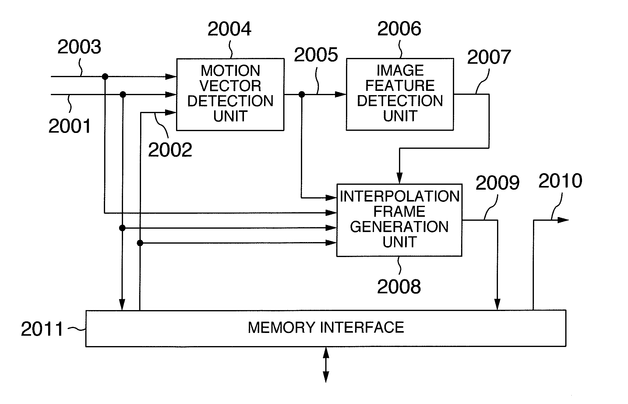
[0037]FIG. 2 schematically shows an example of the frame rate conversion (FRC) unit used 1003 in the first embodiment shown in FIG. 1.

[0038]In FIG. 2 are shown a current frame signal 20...

embodiment 2

[0066]FIG. 16 is a state diagram for explaining the dynamic FRC processing of the video processing apparatus as a second embodiment of this invention. In FIG. 16, components equivalent to those shown in FIG. 9 are indicated with the same reference numerals and their description is omitted.

[0067]In this embodiment are provided three states of FRC operations so as to effectuate a better control of images. In the following is described that part of the FRC operation which differs from the FRC operation according to the first embodiment described above.

[0068]As shown in FIG. 16, the middle mode S201 is an intermediate state between the vector FRC operation and the non-FRC operation. Each of these three states is assumed in accordance with the transition conditions described later. The vector FRC operation (S205), the middle mode operation (S202, S204) or the non-FRC operation (S203) takes place according respectively as the judgment signal 2007 outputted from the image feature detection...

embodiment 3

[0080]FIG. 22 shows a block diagram of a video processing apparatus as a third embodiment of this invention.

[0081]In FIG. 22, components equivalent to those shown in FIG. 1 are indicated with the same reference numerals and their description is omitted.

[0082]According to this embodiment, the most suitable one of plural interpolation procedures can be selected in a switching manner according to different genres of programs such as sports, news, movies, etc.

[0083]Also, the optimal interpolation control can be selected in a wide mode operation.

[0084]In the following is described that part which differs from the first and second embodiments described above.

[0085]In FIG. 22 are shown an event information table (EIT) data 22001, an EIT data processing unit 22002, an EIT judgment signal 22003, a wide mode signal 22004, a dynamic FRC mode selection unit 22005, and a dynamic FRC mode signal 22006.

[0086]In the BS / CS / terrestrial digital TV broadcast, not only video / audio / data signals but also ...


PUM


Abstract

There is provided a video processing apparatus comprising a motion vector detection unit for detecting data on the motions of objects by using at least two frames, an interpolation frame generation unit for generating interpolation frames in the horizontal/vertical and temporal directions in accordance with the motion vectors obtained by the motion vector detection unit, and an image feature detection unit for detecting the features of motions extended over the at least two frames, wherein the procedures, performed by the image feature detection unit, of generating interpolation frames in the horizontal/vertical and temporal directions are switched over in accordance with the features of motions.

Description

INCORPORATION BY REFERENCE[0001]The present application claims priority from Japanese application JP2007-069758 filed on Mar. 19, 2007, the content of which is hereby incorporated by reference into this application.BACKGROUND OF THE INVENTION[0002]This invention relates to a video processing apparatus and more particularly to a technique for effectuating frame rate conversion by using interpolation frames derived from the frames in the video signal.[0003]Recently, an industrial trend has become prevailing that the frame rate conversion technique is used as means for improving the quality of images displayed on a display apparatus by increasing the number of frames in a video signal so as to suppress such unnatural motions in animations as blurs and motion judder or irregularity. In order to obtain a definite improvement on the animation quality, however, interpolation frames with high precision must be generated. A conventional, high-level method of frame interpolation uses the moti...

Claims


Application Information

Patent Timeline
IPC IPC(8): H04N7/01H04N5/14
CPCG06T3/4007G06T7/2013H04N7/014H04N7/0127H04N5/145G06T7/223
Inventor OGINO, MASAHIRONAKAJIMA, MITSUOMIZUHASHI, YOSHIAKITAKANOHASHI, KENTA
Owner MAXELL HLDG LTD
Why Eureka
Try Eureka