METHOD OF PROVIDING A VoIP CONNECTION

a technology of voip connection and connection channel, which is applied in the direction of substation equipment, electrical equipment, wireless commuication services, etc., can solve the problems of large amount of redundant signaling, huge amount of signaling overhead, delay and jitter requirements, etc., and achieves the reduction of control traffic, reducing the overhead of control signaling, and increasing spectral efficiency

Inactive Publication Date: 2008-09-25
LUCENT TECH INC
View PDF3 Cites 10 Cited by
  • Summary
  • Abstract
  • Description
  • Claims
  • Application Information

AI Technical Summary

Benefits of technology

[0010]The present invention helps to reduce control traffic in a VoIP connection. The control signaling overhead is minimized for VoIP users by joint persistent allocation of uplink and downlink. Spectral efficiency is increased by reducing the control signaling overhead and fast deactivation and reactivation of persistently scheduled physical resources in silent periods. As a result, more VoIP users can be supported in a mobile communication system.
[0011]The invention covers an important aspect of the physical layer for wireless VoIP communications. In particular it provides an efficient physical resource allocation for wireless VoIP transmission. While reducing the signaling overhead by means of persistent scheduling, the present invention maintains the flexibility to temporarily deactivate persistent resource allocations in silent periods and to temporarily de-allocate resources of the communication system in silent periods, respectively.

Problems solved by technology

VoIP packets are very small, equally sized and periodically created at constant intervals and face tight delay and jitter requirements.
Considering these characteristics, dynamic scheduling like being used for other data services would lead to an enormous amount of signaling overhead.
Furthermore, the dynamic scheduling of equally sized VoIP packets leads to large amounts of redundant signaling since explicit signaling is used for each packet in order to allocate the same amount of resources at a constant time interval.
One disadvantage of persistent scheduling is the inefficient use of resources.
The allocated resources do not transmit actual VoIP data during these periods but are unavailable to other, dynamically scheduled data.
However, this approach leads to rather large additional explicit signaling messages.

Method used


Image

  • METHOD OF PROVIDING A VoIP CONNECTION
  • METHOD OF PROVIDING A VoIP CONNECTION
  • METHOD OF PROVIDING A VoIP CONNECTION

Examples


Embodiment Construction

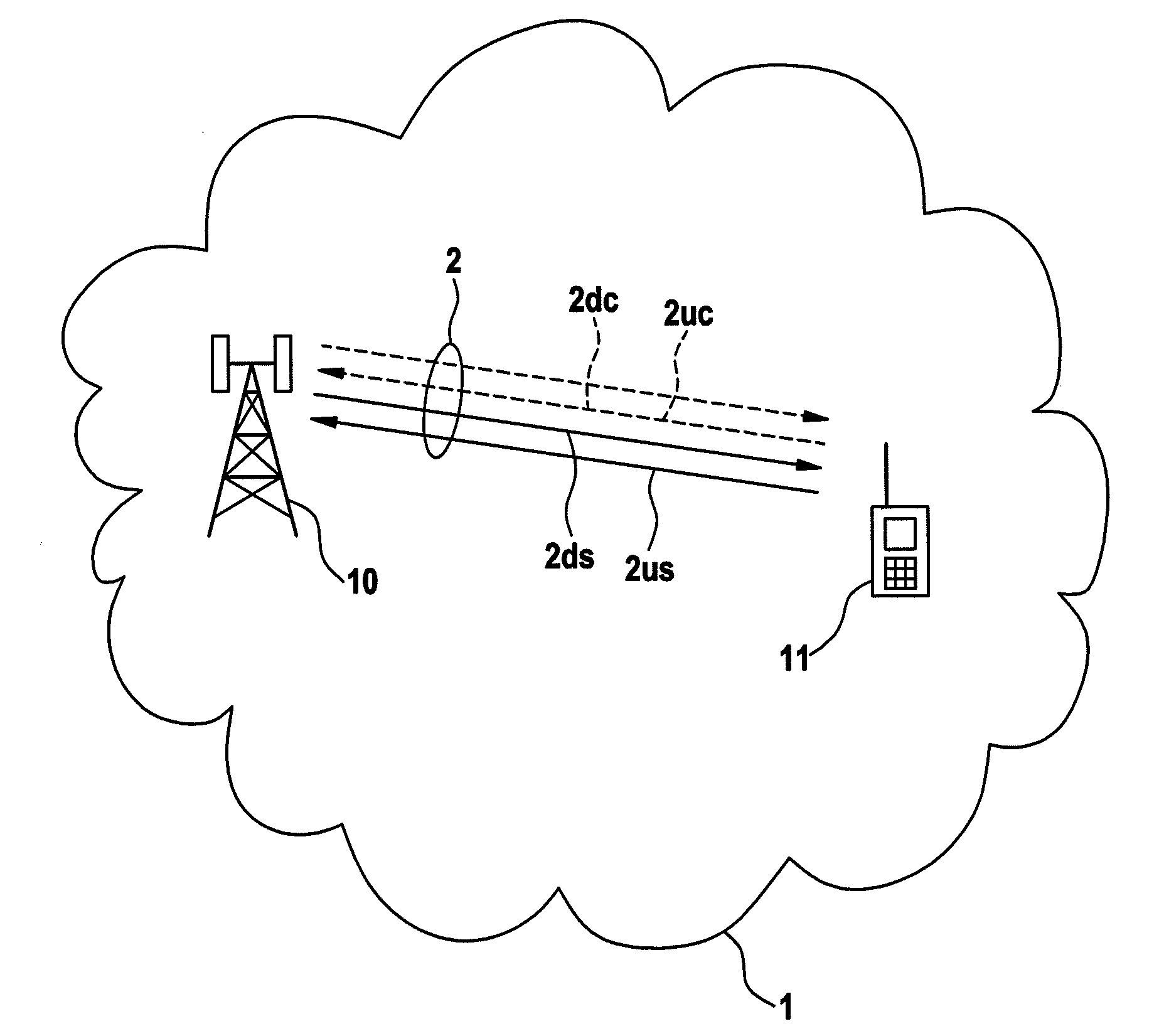
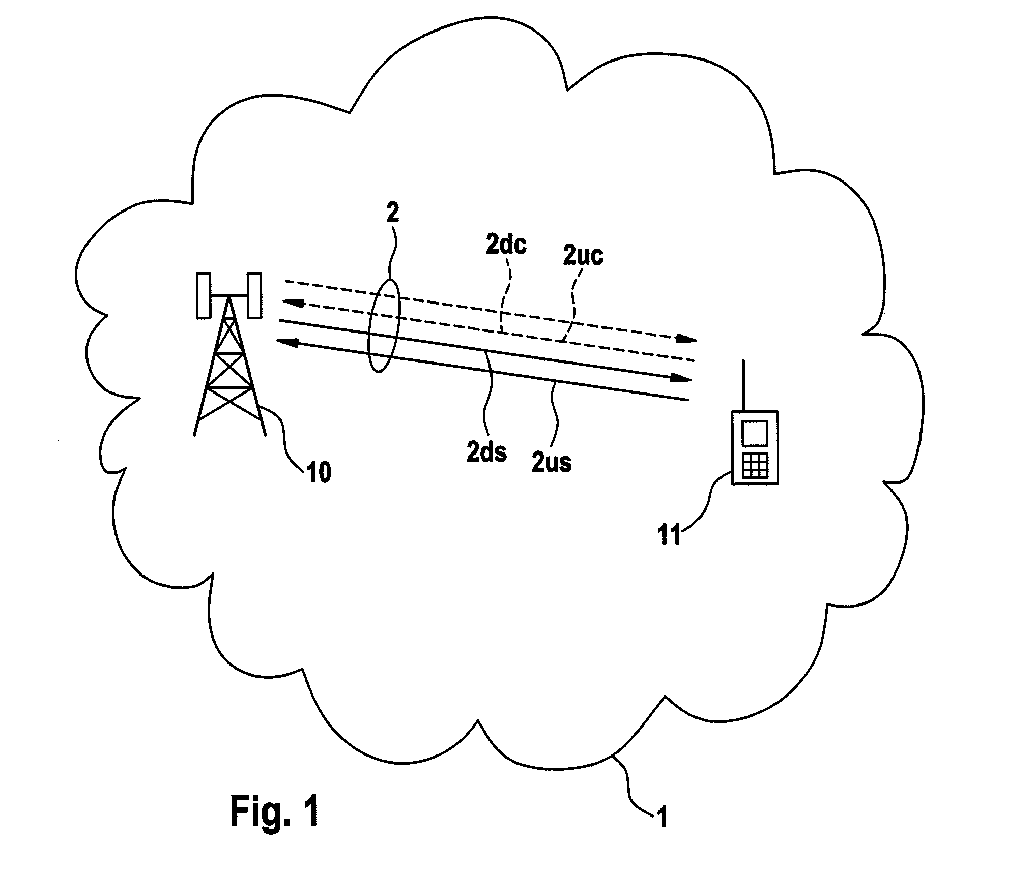
[0028]FIG. 1 shows a packet based wireless communication system 1, a base station 10, a wireless mobile terminal 11, and a wireless communication link 2 between the base station 10 and the terminal 11 comprising a downlink control channel 2dc, an uplink control channel 2uc, a downlink data channel 2ds and an uplink data channel 2us. The letter “s” in the reference signs 2ds and 2us indicates that the data sent on the data channel is “speech”. Preferably, the wireless communication link 2 is a VoIP communication link.

[0029]The packet based wireless communication system 1 may be any system of networks that are suited for the transport of packet-based communication data, for example a UMTS network. The base station 10 provides the sending and receiving functions for the wireless communication link 2 over the air interface. The base station 10 provides the wireless terminal 11 with a connection to other wireless communication networks or with a wireline data network, telephone network l...


PUM


Abstract

This invention concerns a method of providing a VoIP connection through wireless communication links of a packet-based wireless communication system, and a corresponding base station and terminal. The wireless communication links comprise an uplink transmission path (2uc, 2us) from the terminal to the base station, and a downlink transmission path (2dc, 2ds) from the base station to the terminal. Each of the uplink and downlink transmission paths (2uc, 2us, 2dc, 2ds) have a control channel (2uc, 2dc) and at least one data channel (2us, 2ds). Control messages (20d, 21d, 220u, 221u, 230d, 250u, 260u) are generated for scheduling network resources and for suspending and/or re-issuing a persistent grant of network resources allocated to the VoIP connection.

Description

[0001]The invention is based on a priority application EP 07 005775.7 which is hereby incorporated by reference.TECHNICAL FIELD[0002]The present invention relates to a method of providing a VoIP connection through wireless communication links of a packet based wireless communication system, as well as to a base station and a terminal for supporting such VoIP connections through wireless communications links (VoIP=Voice over Internet Protocol).BACKGROUND OF THE INVENTION[0003]In next-generation packet-based wireless systems like UMTS Long-term Evolution, VoIP will be an important service to be supported (UMTS=Universal Mobile Telecommunications System). However, VoIP data has unique traffic characteristics that differ from other packet data services. VoIP packets are very small, equally sized and periodically created at constant intervals and face tight delay and jitter requirements.[0004]Considering these characteristics, dynamic scheduling like being used for other data services wo...

Claims


Application Information

Patent Timeline
Patent Type & Authority Applications(United States)
IPC IPC(8): H04Q7/00H04Q7/20H04W72/12H04W74/02
CPCH04W72/04H04W72/1289H04W72/1263H04W72/23H04W72/12
Inventor SCHNEIDER, MATTHIASFANIUOLO, ANTONELLABACHL, RAINER
Owner LUCENT TECH INC
Why Eureka
Try Eureka