Optical fiber ribbon

a technology of optical fiber and ribbon, applied in the direction of optical fibre, instruments, fibre mechanical structures, etc., can solve the problems of unobtainable favorable flame resistance and screening characteristics

Active Publication Date: 2008-09-25
FURUKAWA ELECTRIC CO LTD
View PDF44 Cites 14 Cited by
  • Summary
  • Abstract
  • Description
  • Claims
  • Application Information

AI Technical Summary

Benefits of technology

[0008]It is an object of the present invention to at least

Problems solved by technology

However, if a fiber coating and a ribbon coating are formed thinner to reduce the diameter of an optical fiber and t

Method used


Image

  • Optical fiber ribbon
  • Optical fiber ribbon
  • Optical fiber ribbon

Examples


first embodiment

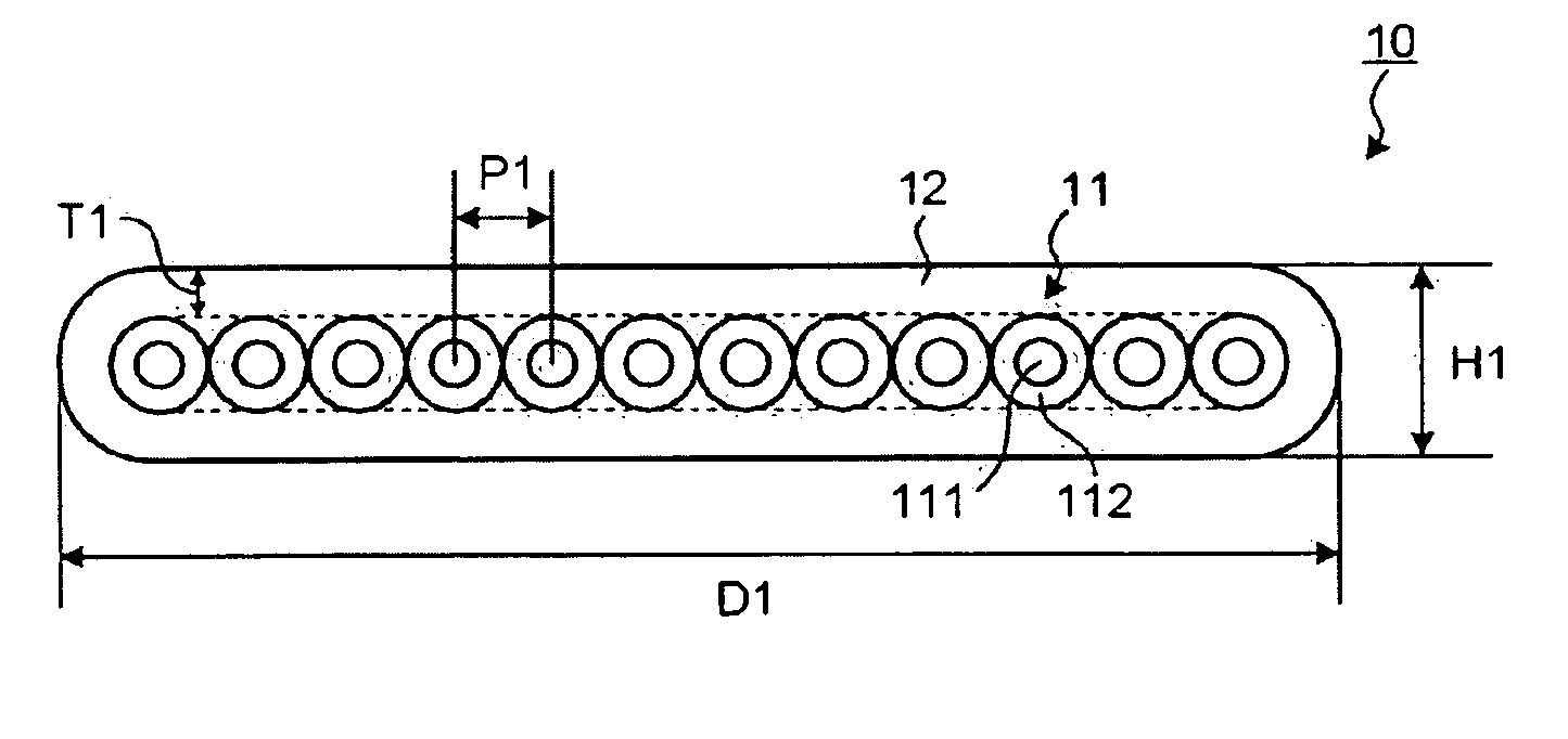
[0020]FIG. 1 is a schematic cross section of an optical fiber ribbon 10 according to the present invention. The optical fiber ribbon 10 is formed by arranging 12 optical fibers 11, each obtained by forming a single layer of fiber coating 112 on the circumference of a glass optical fiber 111, and integrating the optical fibers 11 with a ribbon coating 12.

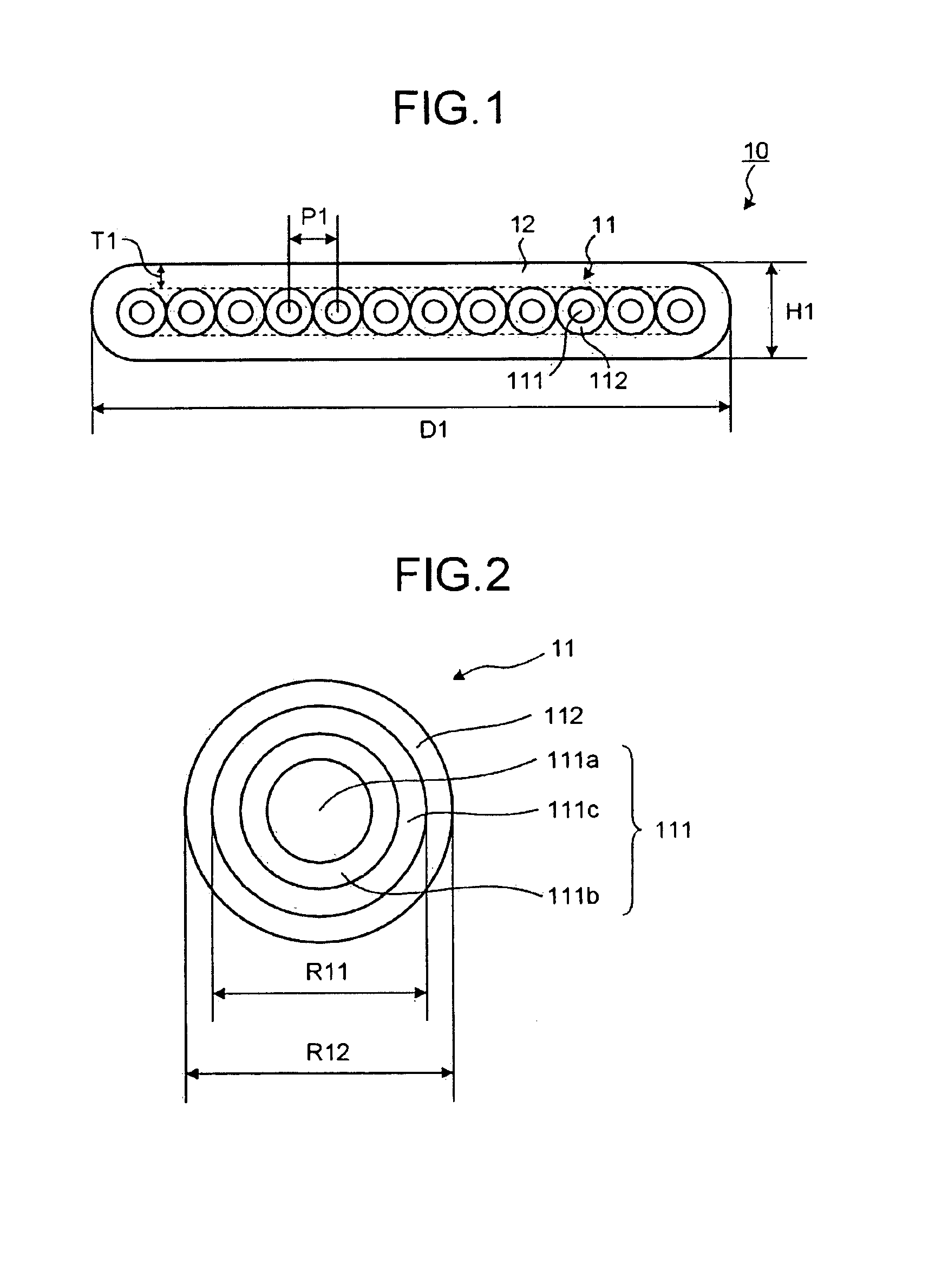
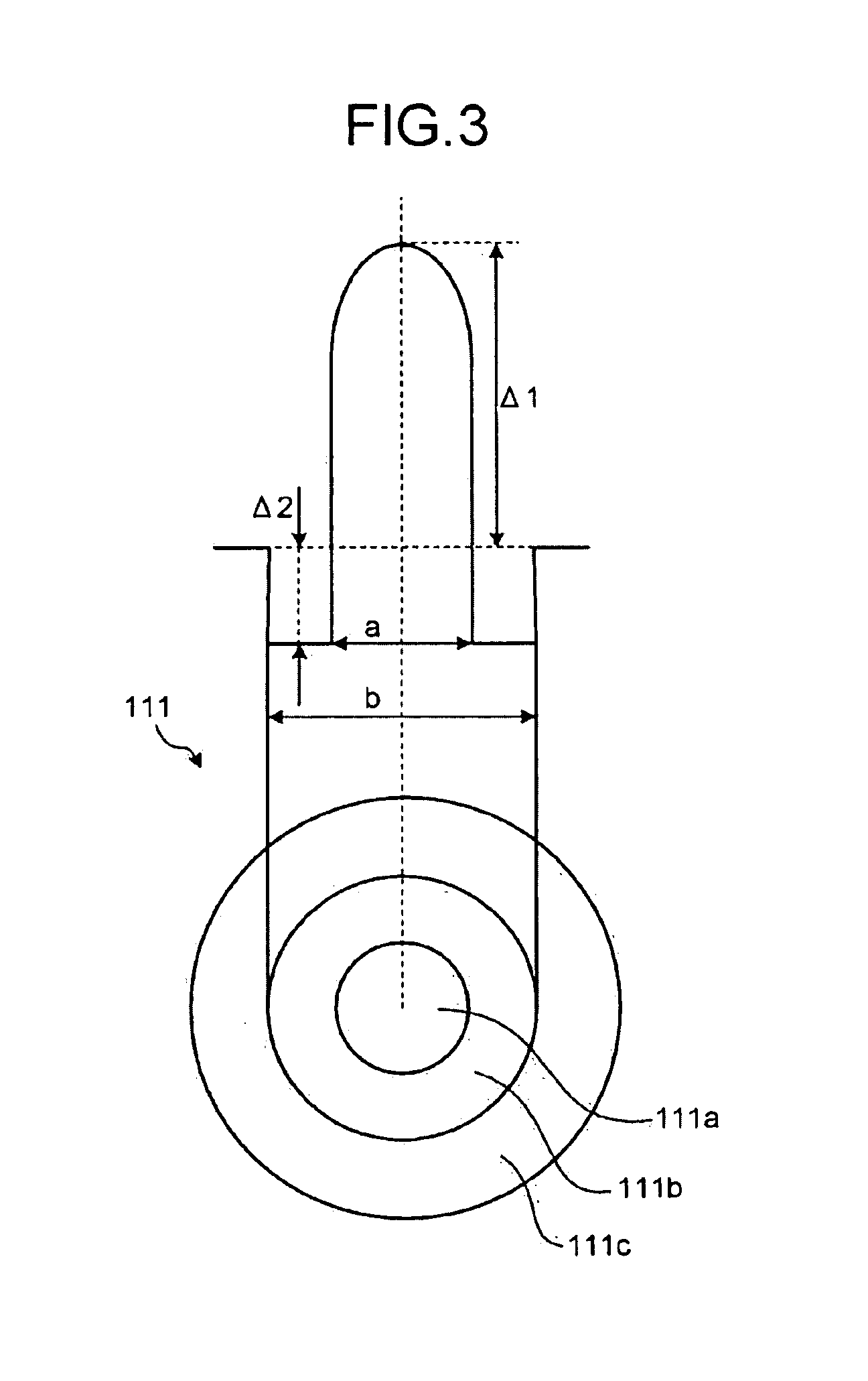
[0021]FIG. 2 is a cross section of the optical fiber 11. The glass optical fiber 111 has an outer diameter R11 of 55 μm to 90 μm smaller than that of a typical optical fiber, i.e., 125 μm. In other words, the outer diameter of the glass optical fiber 111 is reduced to the extent that transmission loss does not increase while installation efficiency improves and possibility of damage in the optical fiber due to bending decreases. The glass optical fiber 111 is explained below.

[0022]The fiber coating 112 has a Young's modulus of 40 kgf to 200 kgf, and is made of a non-flame-resistant ultraviolet curable resin not containing flame resis...

second embodiment

[0034]FIG. 4 is a schematic cross section of an optical fiber ribbon 20 according to the present invention. The optical fiber ribbon 20 is formed by arranging in parallel 12 optical fibers 21, each obtained by forming a fiber coating 212 on the circumference of a glass optical fiber 211, and by integrating the optical fibers 21 with a ribbon coating 22.

[0035]FIG. 5 is a cross section of the optical fiber 21. As with the optical fiber 11, the optical fiber 21 is obtained by forming the fiber coating 212 on the circumference of the glass optical fiber 211. The glass optical fiber 211 includes a center core 211a and a cladding layer 211b formed around the center core 211a, and is a single mode optical fiber having a normal step-type refractive-index profile. An outer diameter R21 of the glass optical fiber 211 is 125 μm.

[0036]The fiber coating 212 includes a non-flame-resistant layer 212a and a flame resistant layer 212b. The non-flame-resistant layer 212a adjacent to the glass optical...


PUM


Abstract

An optical fiber ribbon includes a plurality of optical fibers, each includes a glass optical fiber coated with a fiber coating, that are arranged in parallel, and a ribbon coating that coats the optical fibers arranged in parallel. The optical fiber ribbon has a thickness equal to 300 μm or less. The fiber coating is made of a non-flame-resistant ultraviolet curable resin. The ribbon coating has a thickness equal to 40 μm or more and is made of a flame resistant resin.

Description

CROSS-REFERENCE TO RELATED APPLICATIONS[0001]This application is a continuation of PCT / JP2007 / 069376 filed on Oct. 3, 2007, the entire content of which are incorporated herein by reference.BACKGROUND OF THE INVENTION[0002]1. Field of the Invention[0003]The present invention relates to a flame resistant optical fiber ribbon.[0004]2. Description of the Related Art[0005]In recent years, an optical interconnection system using optical fibers for wiring has been attracting attention as a technology for sending a signal in a transmission device. Usually, such optical fibers are used in a form of an optical fiber ribbon. An optical fiber ribbon is formed by arranging in parallel optical fibers, each obtained by forming a fiber coating made of, for example, an ultraviolet curable resin around the circumference of a glass optical fiber, and then coating the optical fibers at the same time with a ribbon coating made of, for example, an ultraviolet curable resin. A conventional optical fiber r...

Claims


Application Information

Patent Timeline
IPC IPC(8): G02B6/44
CPCG02B6/03627G02B6/02395G02B6/4436G02B6/4403
Inventor INABA, HARUMISUGIZAKI, RYUICHIYAGI, TAKESHI
Owner FURUKAWA ELECTRIC CO LTD
Why Eureka
Try Eureka