Off-axis fiber reinforced composite core for an aluminum conductor

a composite core and aluminum conductor technology, applied in the direction of insulated conductors, cables, power cables, etc., can solve the problems of cable sag, cable sagging, and many problems

Active Publication Date: 2008-09-25
CTC GLOBAL CORP
View PDF80 Cites 39 Cited by
  • Summary
  • Abstract
  • Description
  • Claims
  • Application Information

AI Technical Summary

Benefits of technology

[0006]In light of the above and according to one broad aspect of an embodiment of the present invention, a composite core for an electrical cable is disclosed herein. In one example, the composite core defines a longitudinal axis that defines a center of the composite core. The core comprises a plurality of longitudinally extending reinforcing fibers embedded in a resin matrix, the fibers comprising a tensile strength in excess of glass fibers, the fibers positioned towards the center of the composite core and the fibers oriented substantially parallel to the longitudinal axis. A plurality of off-axis reinforcing fibers are embedded in a resin matrix and surround the longitudinally extending fibers. The off-axis fibers are oriented at an angle relative to the longitudinal axis.
[0007]Further disclosed is another embodiment of a composite core for an electrical cable. In one example, the composite core defines a longitudinal axis that defines a center of the composite core. The composite core comprises a plurality of reinforcing fibers of one or more fiber types embedded in a resin matrix, the one or more reinforcing fiber types having a substantially parallel orientation with respect to the longitudinal axis; and a sheath surrounding the plurality of one or more reinforcing fiber types. In various embodiments, the sheath may or may not be reinforced with fibers, including for example, off-axis fibers.
[0008]An alternate embodiment of a composite core for an electrical cable is disclosed herein. For example, a composite core defining a longitudinal axis that defines a center of the composite core. The core comprises a plurality of reinforcing carbon fibers embedded in a resin matrix, the carbon fibers positioned towards the center of the composite core and the carbon fibers having a su

Problems solved by technology

The inherent physical characteristics of the components of these traditional cables limit ampacity.
However, increasing conductor weight causes numerous problems.
Weight increases due to increased conductor area cause the cable to sag.
In addition,

Method used


Image

  • Off-axis fiber reinforced composite core for an aluminum conductor
  • Off-axis fiber reinforced composite core for an aluminum conductor
  • Off-axis fiber reinforced composite core for an aluminum conductor

Examples


example

[0109]In accordance with another embodiment of the invention, a multi-phase B-stage forming process produces a composite core member from substantially continuous lengths of suitable fiber tows and heat processable resins. In a further step, the composite core member is wrapped with high conductivity aluminum.

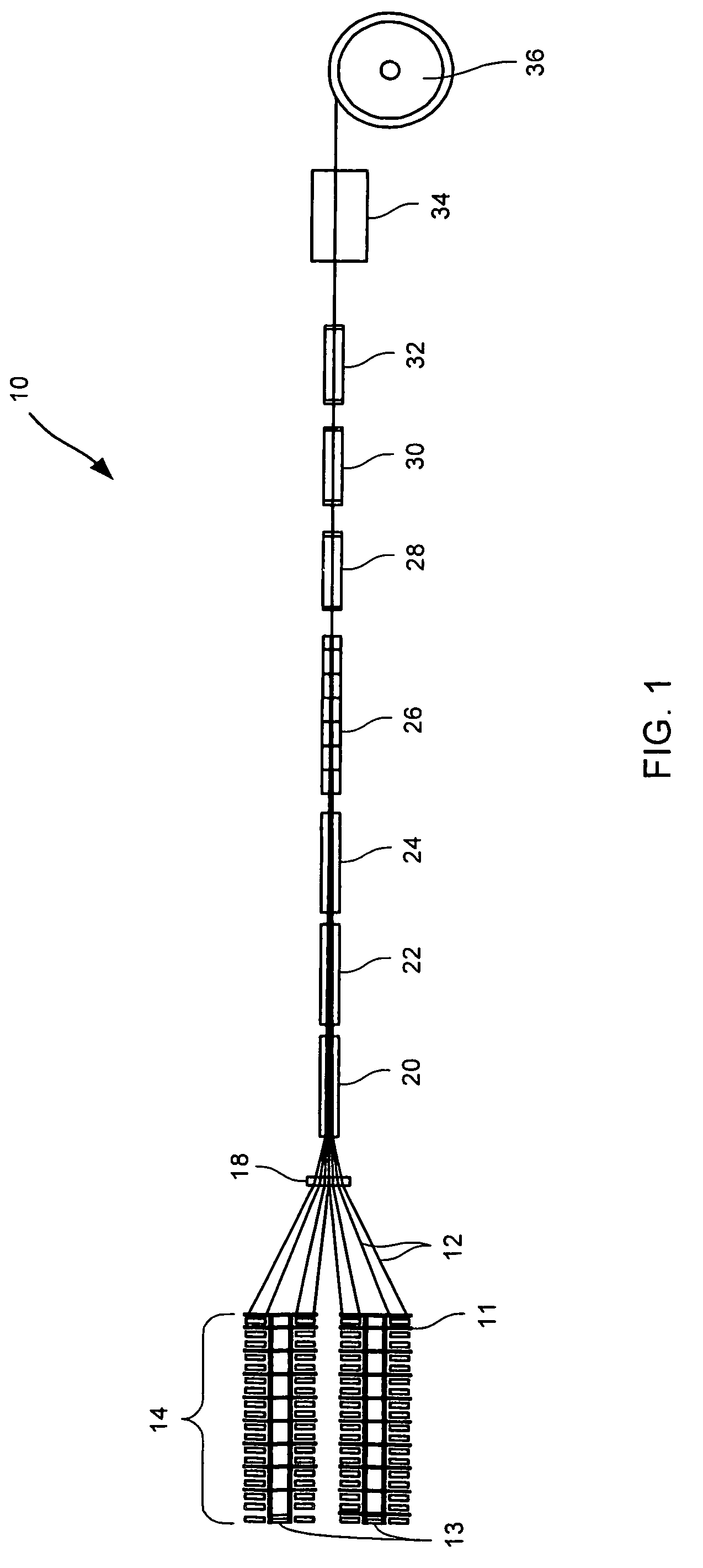
[0110]A process for making composite cores for ACCC cables according to the invention is described as follows. Referring to FIG. 1, the conductor core B-stage forming process of the present invention is shown and designated generally by reference number 10. The B-stage forming process 10 is employed to make continuous lengths of composite core members from suitable fiber tows or rovings and heat processable resins. The resulting composite core member comprises a hybridized concentric core having an inner and outer layer of uniformly distributed substantially parallel fibers.

[0111]In starting the operation, the pulling and winding spool mechanism is activated to commence pulling...

example one

Composite Core

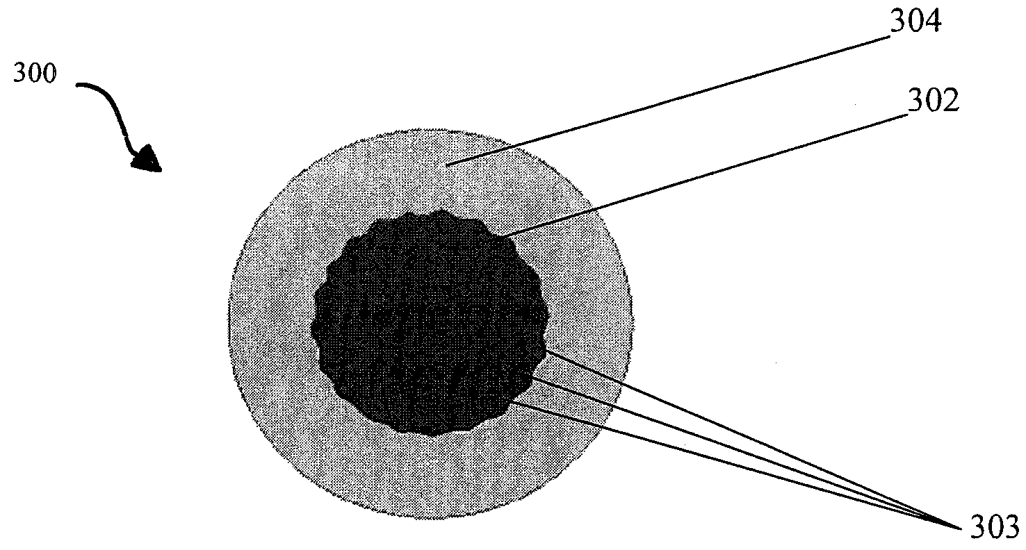
[0173]A particular embodiment of the invention is now described wherein the composite strength member comprises boron free E-glass and carbon with type 13 sizing. E-glass combines the desirable properties of good chemical and heat stability, and good electrical resistance with high strength. The cross-sectional shape or profile is illustrated in FIG. 8 wherein the composite strength member comprises a concentric carbon core encapsulated by a uniform layer of glass fiber composite. In a preferred embodiment the process produces a hybridized core member comprising two different materials.

[0174]The fiber structures in this particular embodiment are 54 ends of E-glass product, 220 yield Veterotex Amer and 28 ends of carbon Torayca T7DOS yield 24K. The resin used is Araldite MY 721 from Vantico.

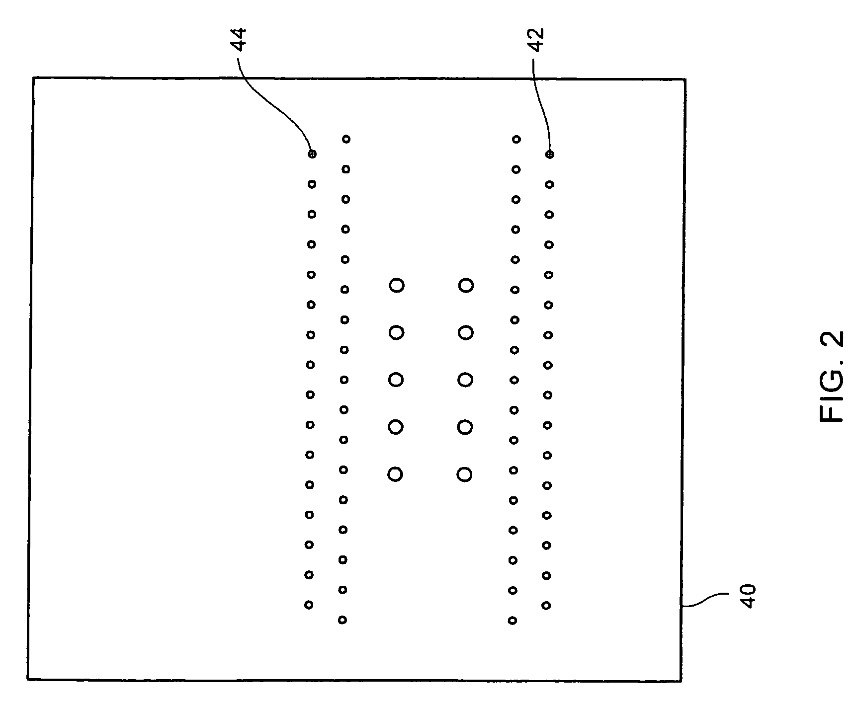
[0175]In operation, the ends of E-glass and carbon are threaded through a fiber tow guide comprising two rows of 32 passageways, two rows inner of 31 passageways and two innermost ro...

example two

Composite Core

[0179]An example of an ACCC reinforced cable in accordance with the present invention follows. An ACCC reinforced cable comprising four layers of components consisting of an inner carbon / epoxy layer, a next glassfiber / epoxy layer and two layers of tetrahedral shaped aluminum strands. The strength member consists of an advanced composite T700S carbon / epoxy having a diameter of about 0.2165 inches, surrounded by an outer layer of R099-688 glassfiber / epoxy having a layer diameter of about 0.375 inches. The glassfiber / epoxy layer is surrounded by an inner layer of nine trapezoidal shaped aluminum strands having a diameter of about 0.7415 inches and an outer layer of thirteen trapezoidal shaped aluminum strands having a diameter of about 1.1080 inches. The total area of carbon is about 0.037 in2, of glass is about 0.074 in2, of inner aluminum is about 0.315 in2 and outer aluminum is about 0.5226 in2. The fiber to resin ratio in the inner carbon strength member is 70 / 30 by w...


PUM

PropertyMeasurementUnit
Angleaaaaaaaaaa
Angleaaaaaaaaaa
Angleaaaaaaaaaa

Abstract

A composite core for an electrical cable, the composite core defining a longitudinal axis that defines a center of the composite core, the core comprising a plurality of longitudinally extending reinforcing fibers embedded in a resin matrix, the fibers oriented substantially parallel to the longitudinal axis and a sheath surrounding the plurality of longitudinally oriented fibers. The sheath may further comprise a plurality of off-axis reinforcing fibers oriented at an angle relative to the longitudinal axis surrounding the longitudinally extending fibers. The sheath may comprise a type of resin, including for example, thermosetting resin or thermoplastic resin.

Description

CROSS REFERENCE TO RELATED APPLICATIONS[0001]This application is a continuation in part of U.S. patent application Ser. No. 10 / 511,881 entitled “ALUMINUM CONDUCTOR COMPOSITE CORE REINFORCED CABLE AND METHOD OF MANUFACTURE” which is a U.S. 371 application of PCT / US03 / 12520, filed Apr. 23, 2003, which claims the benefit of U.S. Provisional Application No. 60 / 374,879, filed Apr. 23, 2002, the disclosures of which are hereby incorporated by reference in their entirety. In relation to this application, applicants claim priority of earlier U.S. provisional application Ser. No. 60 / 374,879 filed in the United States Patent and Trademark Office on Apr. 23, 2002, the entire disclosure of which is incorporated by reference herein.FIELD OF THE INVENTION[0002]The present invention relates to an aluminum conductor composite core (ACCC) reinforced cable and method of manufacture. More particularly, to a cable for providing electrical power having a reinforced fiber thermosetting resin composite co...

Claims


Application Information

Patent Timeline
IPC IPC(8): B32B17/02
CPCB32B15/04B32B27/04H01B5/105H01B7/1825H01B9/006H01B13/0016Y10T428/2938H02G7/056H02G15/06H02G15/18Y10T428/2933Y10T428/294H02G7/04Y10T428/249946Y10T428/24995
Inventor HIEL, CLEMENTKORZENIOWSKI, GEORGEBRYANT, DAVIDPILLING, DOUGLASFERGUSON, WILLIAMBOSZE, ERIC
Owner CTC GLOBAL CORP
Why Eureka
Try Eureka