
Master-slave manipulator system

a manipulator and master technology, applied in the field of master-slave manipulator system, can solve the problems of not being able to separate a hand, requiring the speed of manipulation, and difficult to perform master-slave operation afterward

Active Publication Date: 2008-09-25
HITACHI LTD +1
View PDF15 Cites 276 Cited by
  • Summary
  • Abstract
  • Description
  • Claims
  • Application Information

AI Technical Summary

Benefits of technology

[0014]It is an object of the invention to provide a master-slave manipulator system capable of shifting to a master-slave operation, in which even when clutch manipulation is performed or a camera visual field is moved, the relationship in position and orientation between a slave manipulator working portion projected onto a camera image and manipulation means is maintained and the manipulation means can be manipulated intuitively.
[0015]That is, it is a first object of the invention to provide a master-slave manipulator system, in which even when clutch manipulation is performed to move a position of manipulation means, manipulation means can be readily manipulated while seeing display means and which is excellent in safety, workability, and operability.
[0016]It is a second object of the invention to provide a master-slave manipulator system, in which even when a camera visual field is changed, manipulation means can be readily manipulated while seeing display means and which is excellent in safety, workability, and operability.
[0017]It is a third object of the invention to provide a master-slave manipulator system, in which even when clutch manipulation is performed and a camera visual field is changed, manipulation means can be readily manipulated while seeing display means and which is excellent in safety, workability, and operability.
[0018]It is a fourth object of the invention to provide a master-slave manipulator system, in which while a camera visual field is changed, it is possible to manipulate a manipulator without confusing an operator and to carry out a change in visual field and manipulation of the manipulator conforming to an operator's will at a time, and which is excellent in safety, workability, and operability.
[0023]With the master-slave manipulator system of the invention, it is possible to shift to a master-slave operation, in which even when clutch manipulation is performed or a camera visual field is moved, the relationship in position and orientation between a slave manipulator working portion projected onto a camera image and manipulation means is maintained and the manipulation means can be manipulated intuitively.

Problems solved by technology

However, there are some cases where a speed of manipulation is demanded and it is not desirable to separate a hand or hands from manipulation means, which is being manipulated.
When a camera is to be changed in position, however, the related art involves a problem that a slave manipulator working portion goes out of a screen, and an agreement in position and orientation between the slave manipulator working portion projected onto display means and manipulation means is not taken account of after a visual field is changed, so that a master-slave operation is hard to perform after the visual field is changed.
That is, there is caused a problem in a limit of a moving range of manipulation means and it is desirable to perform a clutch manipulation, in which manipulation means is returned to a position for easy movement, while a position of a slave manipulator is left as it is.
In the case where such clutch manipulation is performed, there is caused a problem that the slave manipulator projected onto display means and manipulation means disagree in position and orientation with each other whereby a direction, in which manipulation is performed by the manipulation means, and a direction, in which the manipulator is moved, disagree with each other.
Such disagreement in direction of movement increases a load on an operator to make it difficult to perform a complex operation.
Further, there is also caused a problem that while a visual field is changed, a slave manipulator, which carries out a work, is suspended to lead to worsening in working efficiency and extending in working hour.
That is, such related art involves a problem that when a camera visual field is changed and clutch manipulation is begun, a difference in orientation between a slave manipulator working portion photographed by a camera and manipulation means is generated to make it hard to perform manipulation.

Method used


Image

  • Master-slave manipulator system
  • Master-slave manipulator system
  • Master-slave manipulator system

Examples


Embodiment Construction

[0037]An embodiment of a master-slave manipulator system according to the invention will be described taking the case of an operation support system with reference to FIGS. 1 to 12.

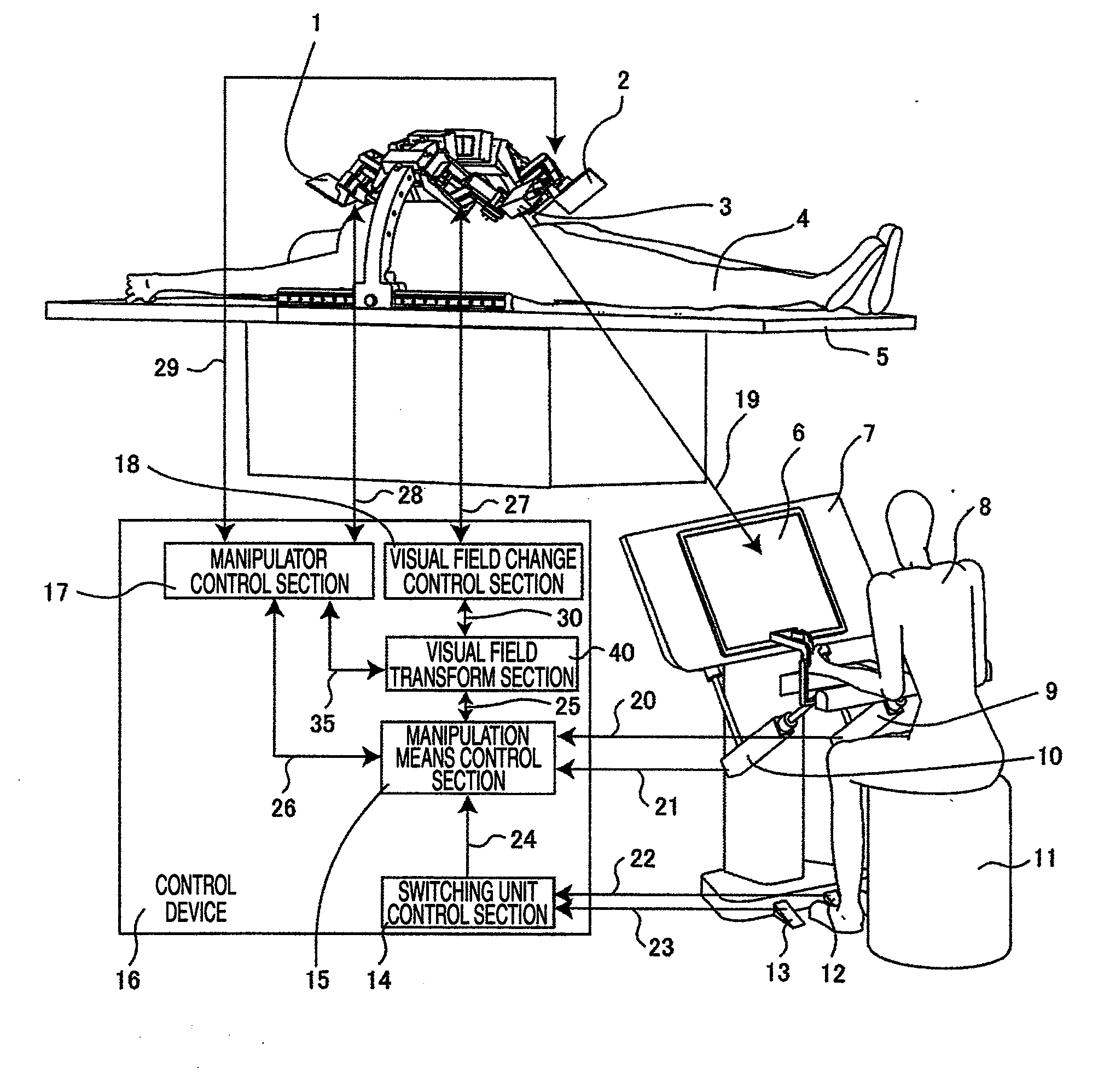
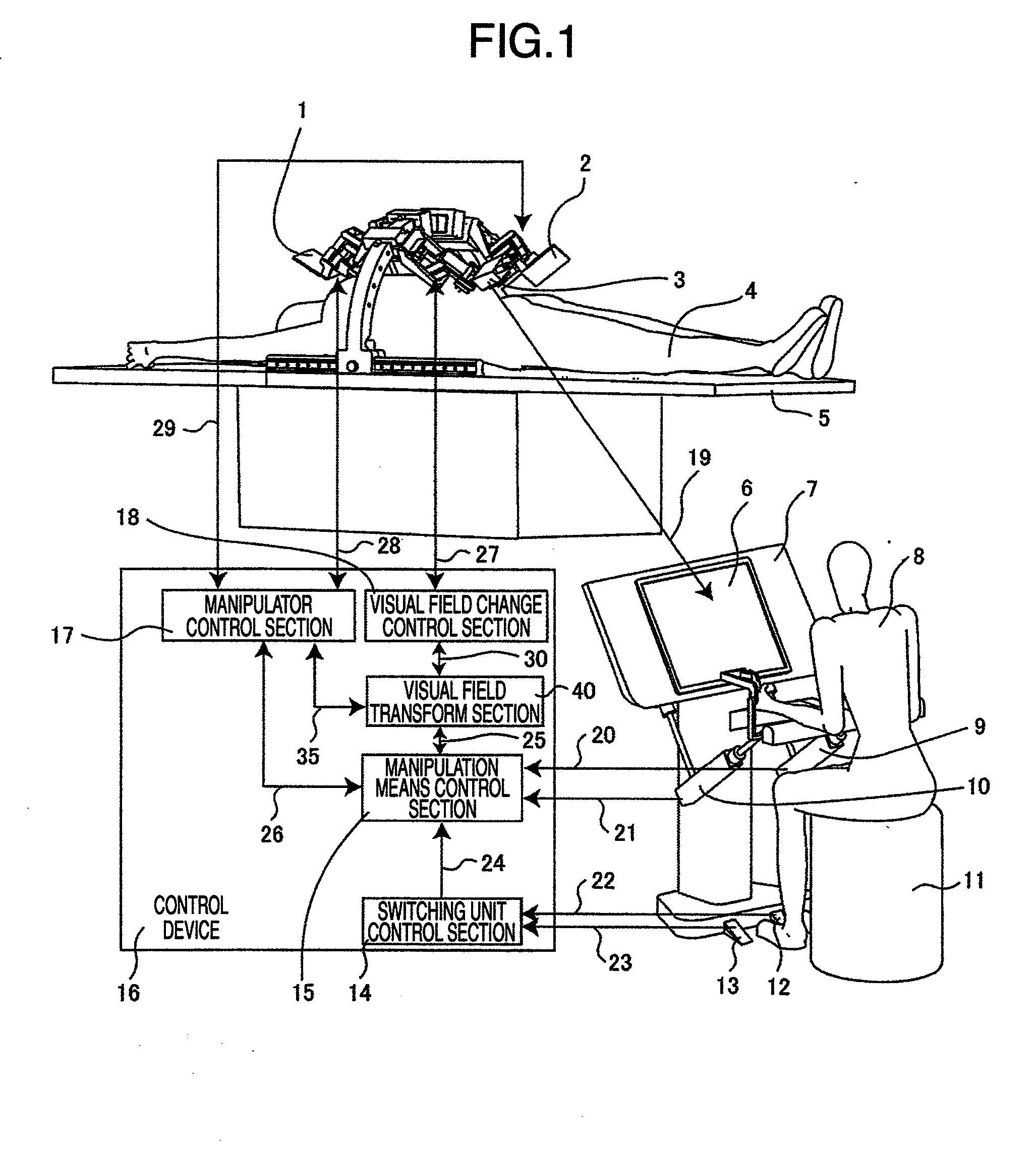
[0038]First, the whole master-slave manipulator system will be described with reference to FIG. 1. FIG. 1 is a view showing the whole construction of the master-slave manipulator system according to an embodiment of the invention.

[0039]A patient 4 is arranged on an operating table 5. Slave manipulators 1, 2 and an endoscope manipulator 3, which are mounted above the operating table 5, are arranged to be directed toward an affected part of the patient 4. The endoscope manipulator 3 is constructed such that an endoscope being observation means is held by a manipulator, which serves as endoscope visual field changing means. A picture imaged by the endoscope held by the endoscope manipulator 3 passes through a transmission path 19 to be displayed on a monitor 6 being display means arranged on a master console...


PUM


Abstract

In a master-slave manipulator system, manipulation device can be manipulated intuitively even when clutch manipulation is performed. A master-slave manipulator system includes: mode switching device for switching between a master-slave mode, in which the slave manipulator is controlled, and an observation device visual field tracking clutch mode, in which transmission of an operation command to the slave manipulator from the manipulation device is cut off to move the manipulation device to an optional position and orientation; a switching unit control section that reads a signal of the mode switching device to forward a mode signal to the manipulation device control section; and a visual field transform section that forwards a third control command to the manipulator control section and forwards a fourth control command to the visual field change control section on the basis of an operation command read by the manipulation device control section at the time of the observation device visual field tracking clutch mode so as to make an agreement between a direction of motion of an image of the slave manipulator displayed on the display device and a direction of manipulation of the manipulation device.

Description

BACKGROUND OF THE INVENTION[0001]The present invention relates to a master-slave manipulator system.[0002]Many master-slave manipulator systems have been developed, in which an operator manipulates manipulation means and a slave manipulator is operated in accordance with the manipulation. When a slave manipulator is operated by manipulation means while an object and the slave manipulator are seen with a camera, which comprises observation means, it is sometimes desirable to operate not only the slave manipulator but also the camera itself.[0003]In the case where a slave manipulator being operated is one in number, there is a method, in which manipulation means associated with the slave manipulator is manipulated by the right hand and manipulation means associated with a camera is moved by the left hand. Also, a system is developed, in which in the case where two slave manipulators are operated by two associated manipulation means with the use of the both hands, the hands are separat...

Claims


Application Information

Patent Timeline
IPC IPC(8): G05B19/00
CPCA61B19/2203A61B19/5212A61B19/5225G05B2219/40617B25J9/1689G05B19/427G05B2219/39389A61B2019/2223A61B90/361A61B34/30A61B34/37A61B90/37
Inventor KISHI, KOSUKEHASHIZUME, MAKOTO
Owner HITACHI LTD
Learn More