Remote Performance Monitor and Remote Performance Monitoring Method

a technology of performance monitor and monitor, which is applied in the direction of ventilation system, heating type, instruments, etc., can solve the problems of inability to achieve the management objective, poor accuracy of the conventional air-conditioning system, and difficulty in achieving the management objective, so as to reduce the sum of energy consumed

Inactive Publication Date: 2008-09-25
KK TOSHIBA
View PDF36 Cites 58 Cited by
  • Summary
  • Abstract
  • Description
  • Claims
  • Application Information

AI Technical Summary

Benefits of technology

[0012]According to an aspect of the present invention, a remote performance monitor configured to acquire monitoring data concerning an air-conditioning System of a monitoring target building and to determine an operating condition of the air-conditioning system, the remote performance monitor comprises a monitoring data receiver which receives monitoring data from a monitoring data collecting apparatus in the monitoring target building, wherein the monitoring data is data concerning performance characteristics of air-conditioning machines installed in the air-conditioning system of the monitoring target building, a characteristic function calculator which calculates a characteristic function for the monitoring target building and for each of the air-conditioning machines based on the monitoring data and an operating condition calculator which calculates operating condition data to minimize a sum of amounts of energy consumed by the air-conditioning mach

Problems solved by technology

In this way, the cause of unachieved management objective is inferred when the operating condition of the facility does not reach the management objective condition.
Meanwhile, a conventional air-conditioning system has poor accuracy caused by handling a fluid.
Accordingly, the conventional air-conditioning system had problems of disabilities to detect a predictor of breakdown, to abs

Method used


Image

  • Remote Performance Monitor and Remote Performance Monitoring Method
  • Remote Performance Monitor and Remote Performance Monitoring Method
  • Remote Performance Monitor and Remote Performance Monitoring Method

Examples


Embodiment Construction

(Remote Performance Monitoring System)

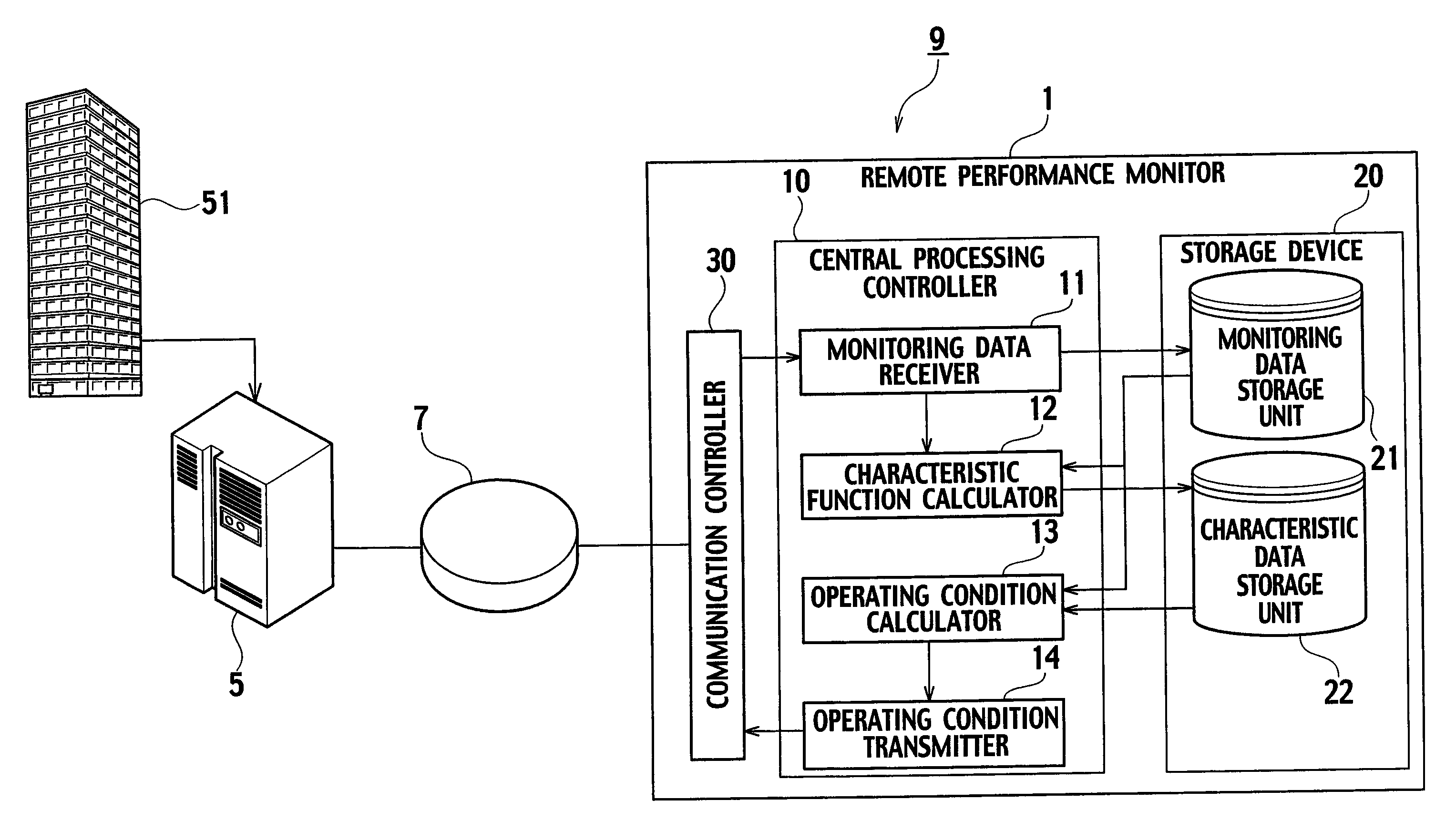
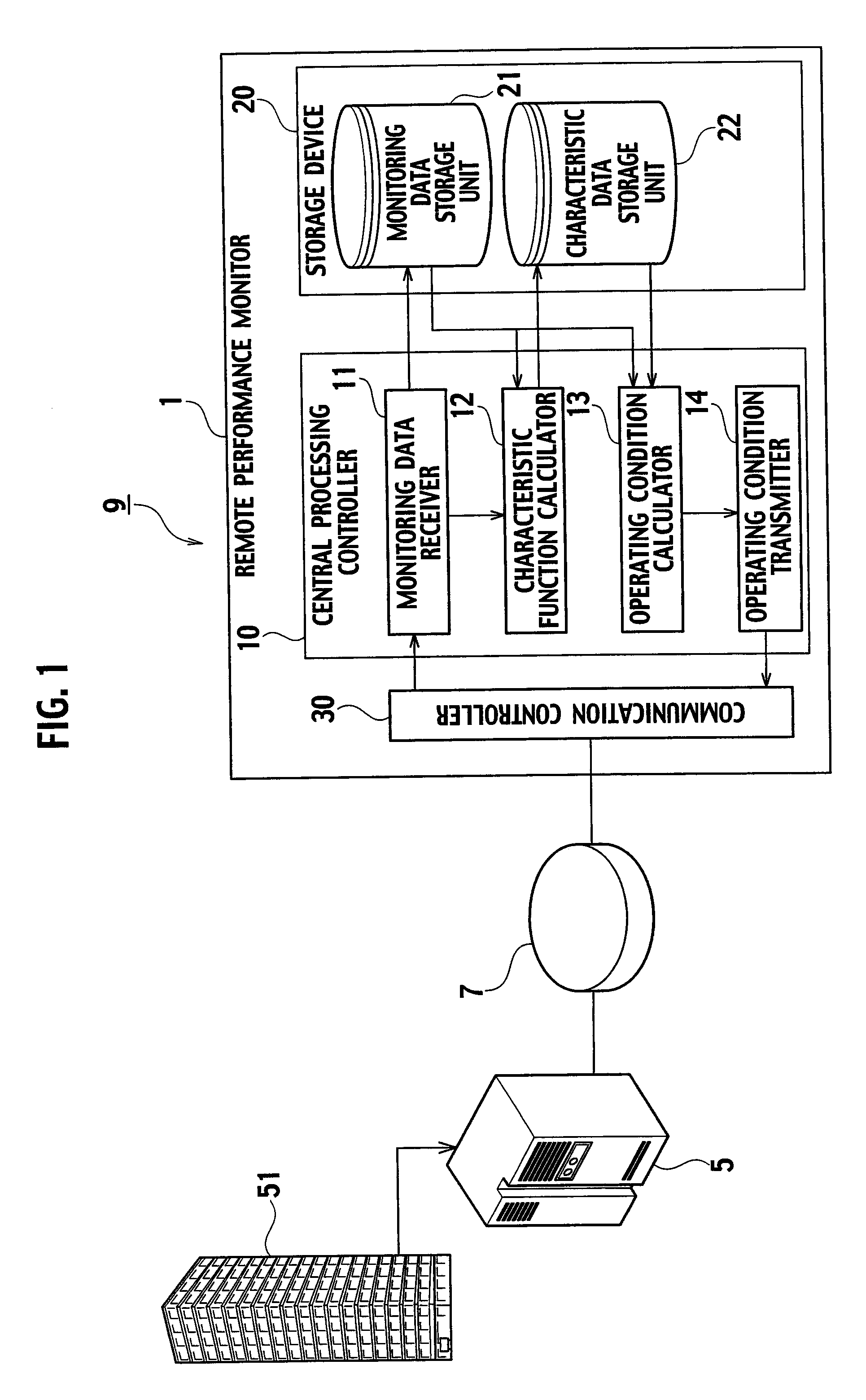
[0028]FIG. 1 is a system configuration view of a remote performance monitoring system 9 according to an embodiment of the present invention. The remote performance monitoring system 9 includes a monitoring target building 51, a monitoring data collecting apparatus 5, and a remote performance monitor 1. The monitoring data collecting apparatus 5 monitors the monitoring target building 51. In FIG. 1, the remote performance monitoring system 9 includes the single monitoring target building 51 and the single monitoring data collecting apparatus 5. Alternatively, the remote performance monitoring system 9 may include multiple monitoring target buildings 51 and multiple monitoring data collecting apparatuses 5. The monitoring data collecting apparatus 5 and the remote performance monitor 1 are mutually connected trough a communication network 7 such as the Internet.

[0029]The monitoring target building 51 includes air-conditioning machines concerning a...


PUM


Abstract

A remote performance monitor to acquire monitoring data concerning an air-conditioning system of a monitoring target building and to determine an operating condition of the air-conditioning system, the remote performance monitor comprises a monitoring data receiver (11), a characteristic function calculator (12) and an operating condition calculator (13). The monitoring data receiver (11) receives monitoring data from a monitoring data collecting apparatus in the monitoring target building. The monitoring data is data concerning performance characteristics of air-conditioning machines installed in the air-conditioning system of the monitoring target building. The characteristic function calculator (12) calculates a characteristic function for the monitoring target building and for each of the air-conditioning machines based on the monitoring data. The operating condition calculator (13) calculates operating condition data to minimize a sum of amounts of energy consumed by the air-conditioning machines by using the characteristic function.

Description

BACKGROUND OF THE INVENTION[0001]1. Field of the Invention[0002]The present invention relates to a remote performance monitor and a remote performance monitoring method configured to acquire monitoring data concerning an air-conditioning system of a monitoring target building and to determine an operating condition of the air-conditioning system.[0003]2. Description of the Related Art[0004]Numerous techniques have heretofore been disclosed concerning remote monitoring, which is to monitor a monitoring target device from a place away from a site where the monitoring target device is installed. The techniques concerning this remote monitoring have also been applied to the purpose of monitoring building facilities such as an air-conditioning system.[0005]Along the development in the communication technology, there has been a technique to acquire necessary signals from an air-conditioning system and to transmit the signals to a remote monitoring center in the distance. In the past, it w...

Claims


Application Information

Patent Timeline
IPC IPC(8): G01M1/38F24F12/00
CPCF24F11/0086F24F2011/0094F24F2011/0068F24F11/30F24F11/56F24F11/47F24F11/64F24F11/46F24F11/62G06Q50/10F24F2110/12F24F2110/22F24F2140/60
Inventor YONEZAWA, KENZOTAKAGI, YASUOITO, YASUYUKIMURAKAMI, YOSHIKINISHIMURA, NOBUTAKADONEN, NOBUYUKI
Owner KK TOSHIBA
Why Eureka
Try Eureka