
Hardware Object Request Broker on a Chip for Generating Separate Control and Data Channels for Improved Throughput Efficiency

a hardware object and request broker technology, applied in the field of middleware techniques, can solve the problems of high power consumption of a given throughput and substantial bandwidth overhead, and achieve the effect of reducing bandwidth overhead

Inactive Publication Date: 2008-09-25
VIRGINIA TECH INTPROP INC
View PDF6 Cites 7 Cited by
  • Summary
  • Abstract
  • Description
  • Claims
  • Application Information

AI Technical Summary

Benefits of technology

[0010]It is therefore an object of the present invention to provide a structure and method for reducing the bandwidth overhead from using middleware with embedded devices.

Problems solved by technology

However, for embedded devices this architectural assumption highlights inefficiencies that lead to higher power consumption for a given throughput.
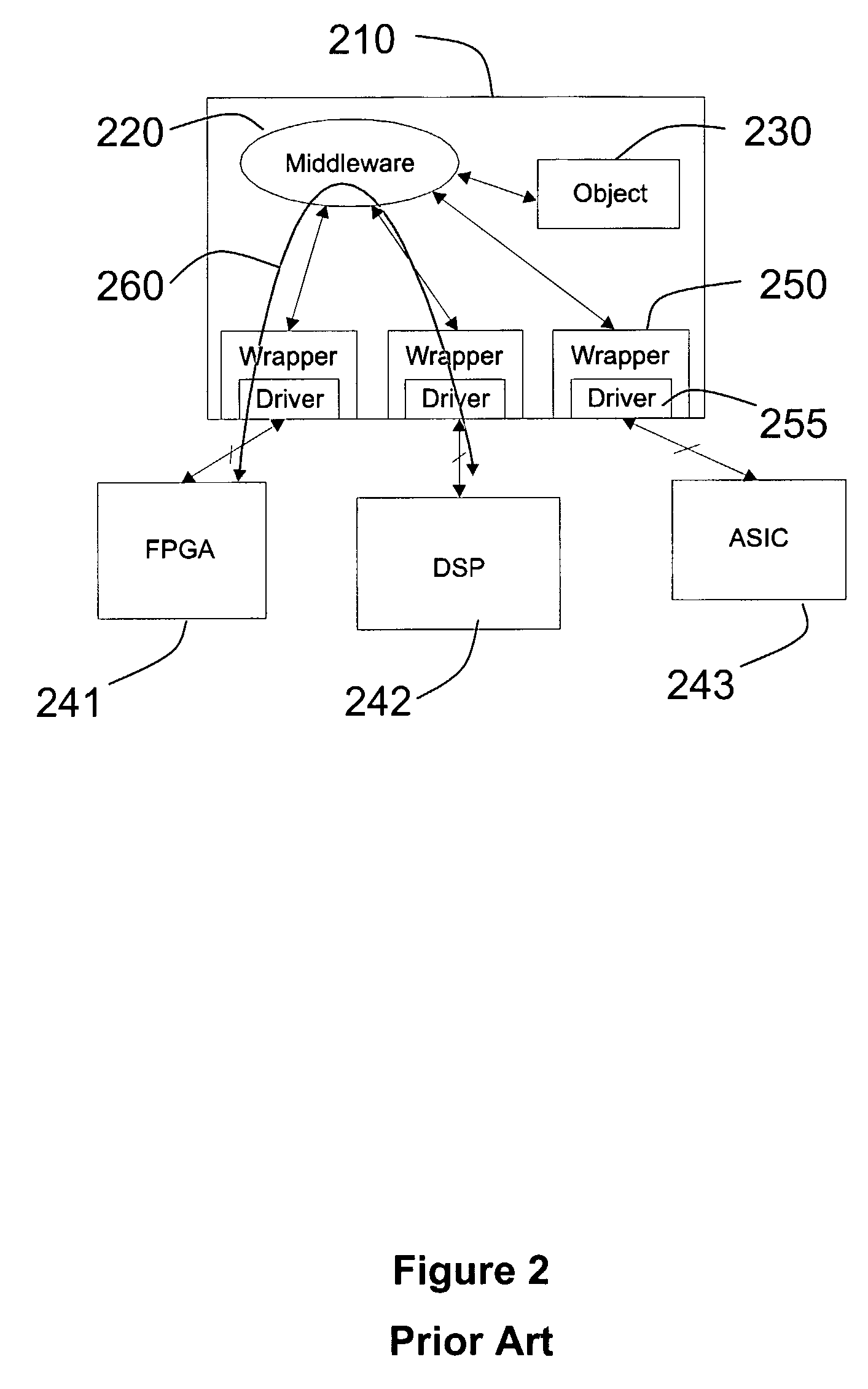
In order to obtain interoperability, the data flowing from one embedded device to another is channeled through the on-board computer, resulting in a substantial bandwidth overhead.

Method used


Image

  • Hardware Object Request Broker on a Chip for Generating Separate Control and Data Channels for Improved Throughput Efficiency
  • Hardware Object Request Broker on a Chip for Generating Separate Control and Data Channels for Improved Throughput Efficiency
  • Hardware Object Request Broker on a Chip for Generating Separate Control and Data Channels for Improved Throughput Efficiency

Examples


Embodiment Construction

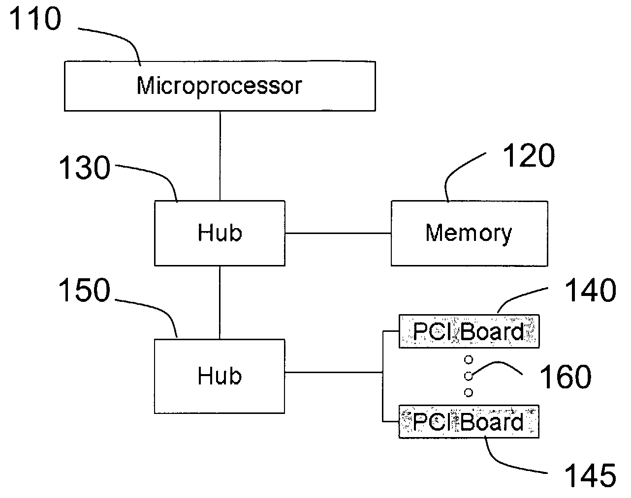
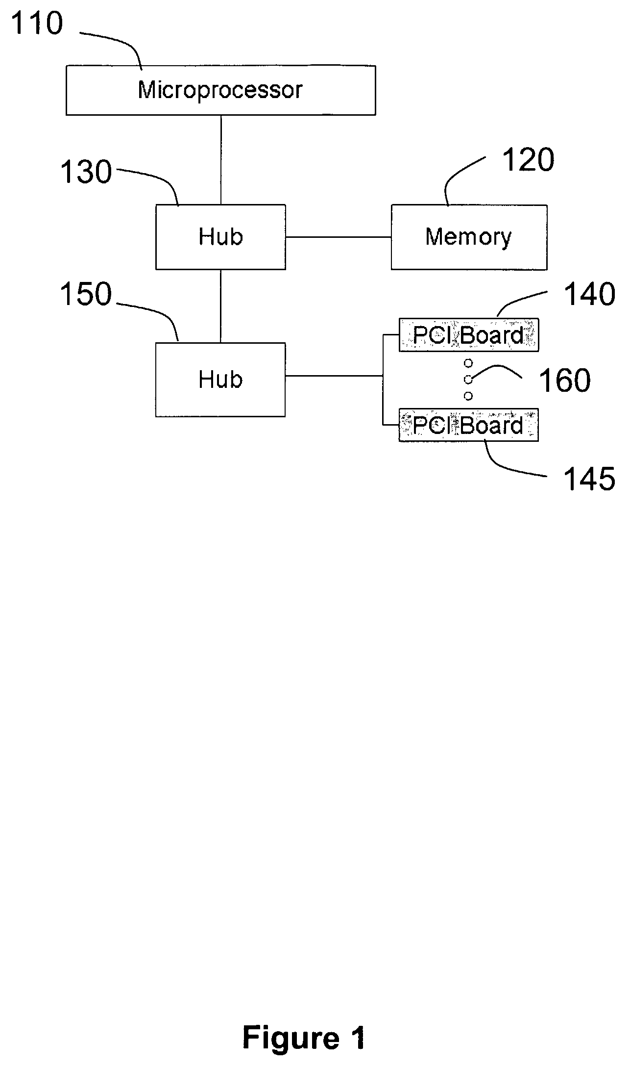
[0026]In the case of embedded devices, a basic boundary constraint arises because of the limited ability of the system to support communications between different devices when a microprocessor is used as the core component for interconnections. FIG. 1 shows the basic architecture of a typical personal computer having a microprocessor 110, a memory 120 connected to the microprocessor 110 through a hub 130, and two embedded devices (not shown) residing on PCI boards 140 and 145 (or equivalent structures), respectively, and connected to microprocessor 110 through a hub 150. The two embedded devices can communicate directly through the use of the bus 160. Therefore, the maximum sustainable rate, C, that can be supported by the system is the bus delay, or

C∝1τbus

[0027]However, when the microprocessor 110 is used to inter-connect these embedded devices, the data must be transported from an embedded device to the microprocessor 110 and then back to the target embedded device. Assuming that ...


PUM


Abstract

A method and apparatus are disclosed for separating the functionality of middleware (320) in a device with embedded resources (341,342) so that data transfer between embedded resources used by an object (330) resident in a general purpose processor (310) of the device takes place directly, thereby minimizing bandwidth overhead at the general purpose processor. The control interface (371,372) for an embedded resource resides in the general purpose processor and uses the device driver of the embedded resource, whereas the data interface (381,382) is outside the general purpose processor and provides direct communication with a switch matrix (360) serving each embedded resource.

Description

BACKGROUND OF THE INVENTION[0001]1. Field of the Invention[0002]The present invention generally relates to middleware techniques for tying together different software objects, and more particularly to hardware techniques for enhancing middleware in devices with embedded resources.[0003]2. Background Description[0004]Middleware is software that connects two or more otherwise separate applications across the Internet or local area networks, enabling the seamless integration of the separate applications. Typically, middleware provides services for managing security, access and information exchange so that a user of one application, having satisfied the security and access requirements of the application, is able to communicate with another application without separately satisfying the security and access requirements of the other application. Middleware hides the underlying complexity of managing the interaction between remote resources, thereby smoothing the development path for new n...

Claims


Application Information

Patent Timeline
Patent Type & Authority Applications(United States)
IPC IPC(8): G06F9/54G06F9/46
CPCG06F9/541G06F9/465
Inventor REED, JEFFREY H.ROBERT, PABLO M.
Owner VIRGINIA TECH INTPROP INC
Learn More