Arrangement for Propelling an Aircraft, Aircraft and Outlet Nozzle for a Jet Engine

a jet engine and jet engine technology, applied in the direction of machines/engines, vessel construction, marine propulsion, etc., can solve the problems of increased detection risk, increased temperature and thermal stress of the nozzle, and pronounced cold and hot bands on the surface of the outlet nozzle, so as to reduce the temperature and the ir signature of the wall structure, the effect of reducing the temperature of the wall structur

Inactive Publication Date: 2008-10-02
VOLVO AERO CORP
View PDF43 Cites 19 Cited by
  • Summary
  • Abstract
  • Description
  • Claims
  • Application Information

AI Technical Summary

Benefits of technology

[0012]With a hole configuration of this kind, the temperature of the wall structure is reduced and with it its IR signature.
[0013]According to a further development of the previous embodiment, the wall structure is so arranged that a cross-sectional area through the gas duct for the fan flow reduces successively in the direction of the outlet from the outlet nozzle. The quantity of fan air that is forced into the cooling openings in the wall structure is increased in this way, with an associated further reduction in the temperature and the IR signature of the wall structure.
[0014]According to another preferred embodiment, the wall structure is designed to absorb thermal loadings, and a structural part which comprises the internal surface that defines the fan duct is designed to absorb mechanical loadings during operation. This offers possibilities for utilizing lighter materials, such as composites, in the external wall / sleeve of the outlet nozzle.

Problems solved by technology

Such hot bands lead to an increased risk of detection as a consequence of an increased IR signature.
Cold and hot bands can also give rise to thermal stresses in the nozzle.
The above-mentioned problem of cold and hot bands on the surfaces of the outlet nozzle is particularly pronounced when the internal surface exhibits a form such that at least one part of the fan flow is deflected.
The above-mentioned problem of cold and hot bands on the surfaces of the outlet nozzle is particularly pronounced when the internal surface exhibits a form such that at least a proportion of the gas emerging from the jet engine is deflected.

Method used


Image

  • Arrangement for Propelling an Aircraft, Aircraft and Outlet Nozzle for a Jet Engine
  • Arrangement for Propelling an Aircraft, Aircraft and Outlet Nozzle for a Jet Engine
  • Arrangement for Propelling an Aircraft, Aircraft and Outlet Nozzle for a Jet Engine

Examples


Embodiment Construction

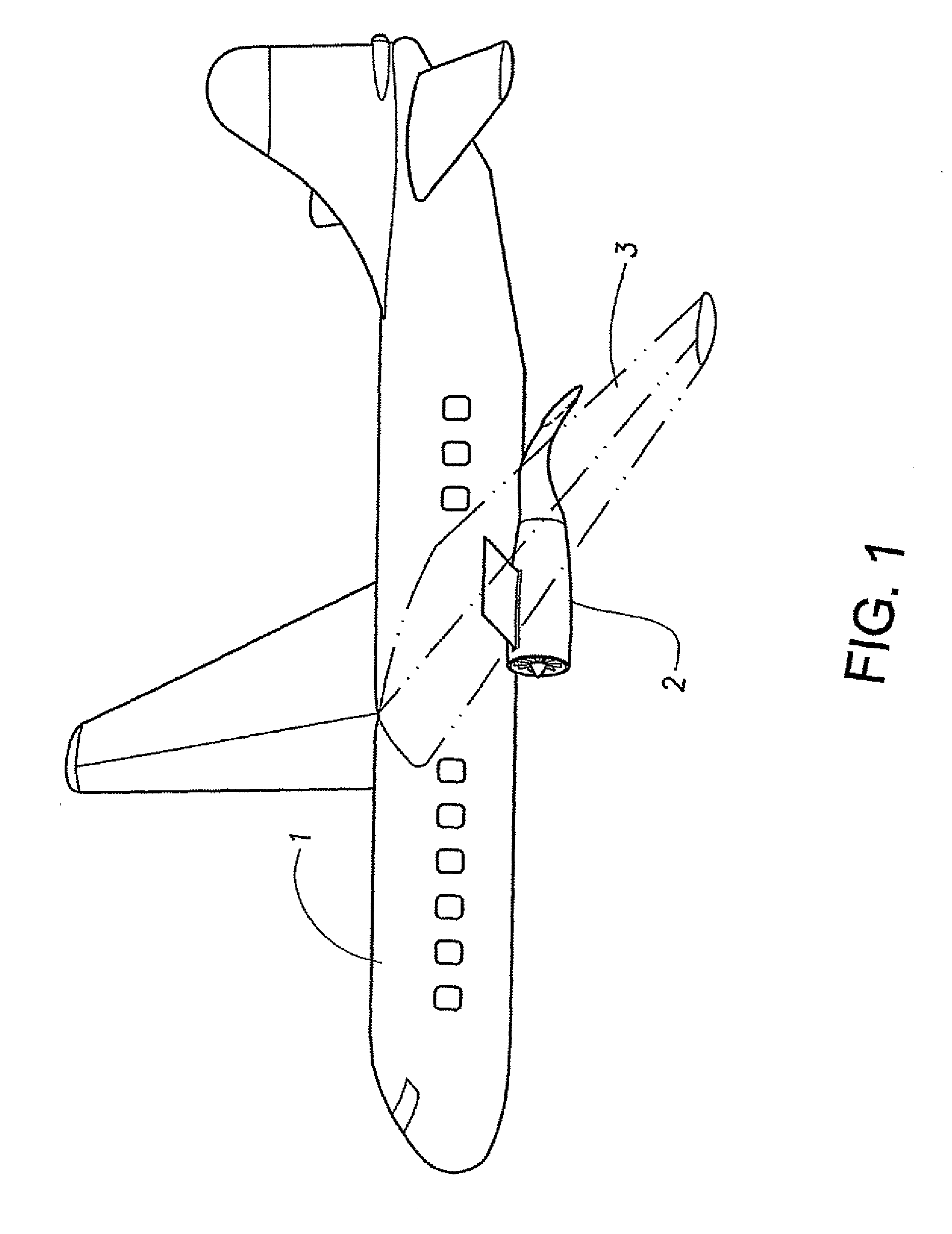
[0027]An aircraft 1 is depicted schematically in FIG. 1 as a perspective view. An arrangement 2 for propelling the aircraft 1 comprising a jet engine 4, see FIG. 2, is mounted under a wing 3.

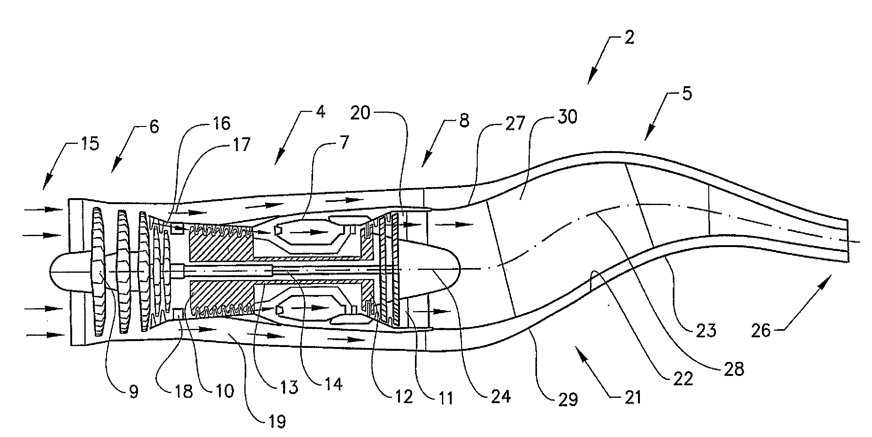
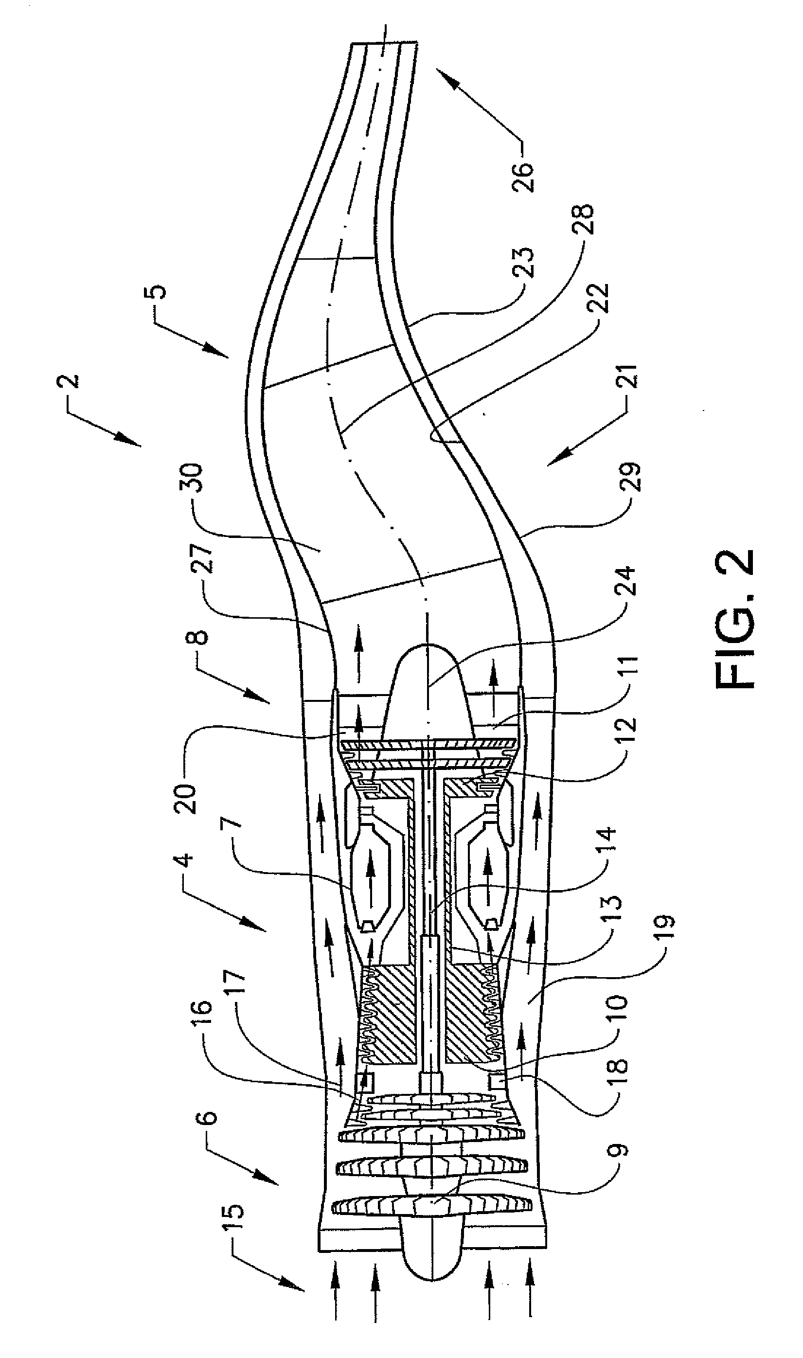
[0028]The propulsion arrangement 2 is depicted in FIG. 2 as a cross-sectional view. The propulsion arrangement 2 comprises the jet engine 4 and an outlet nozzle 5 arranged downstream of the jet engine 4. The jet engine 4 is of the double-flow type and has double rotors.

[0029]The jet engine 4 comprises a compressor section 6 for compression of the incoming air, a combustion chamber 7 for combustion of the compressed air and a turbine section 8 arranged after the combustion chamber, which turbine section is rotationally connected to the compressor section in order to drive the latter with the help of the energy-rich gas from the combustion chamber. The compressor section 6 comprises a low-pressure part 9, or a fan, and a high-pressure part 10. The turbine section 8 comprises a low-pressure part 11...


PUM


Abstract

The invention relates to an arrangement for propelling an aircraft comprising a jet engine and an outlet nozzle arranged downstream of the jet engine. The jet engine is of a type which generates an internal core flow and an external fan flow. A part of the outlet nozzle has an internal surface which defines a gas duct for the fan flow. The aforementioned part of the outlet nozzle includes a wall structure that is arranged at a distance from the internal surface such that it separates the gas duct for the fan flow from an internal gas duct for the core flow.

Description

BACKGROUND AND SUMMARY[0001]The present invention relates to an arrangement for propelling an aircraft comprising a jet engine and an outlet nozzle arranged downstream of the jet engine, the jet engine being of a type which generates an internal core flow and an external fan flow, a part of the outlet nozzle having an internal surface which defines a gas duct for the fan flow. The invention also relates to a correspondingly executed outlet nozzle.[0002]The expression “core flow” is used here to denote a radial inner gas flow which originates from the combustion chamber of the jet engine. The core flow accordingly has a high energy content. The expression “fan flow” is used here to denote a radial outer gas flow (air flow) which flows in an outer duct in the jet engine, which extends from a front fan in the jet engine and past the combustion chamber. The fan flow is also known as the bypass flow. The jet engine is thus of the double-flow type.[0003]Previously disclosed is the protect...

Claims


Application Information

Patent Timeline
Patent Type & Authority Applications(United States)
IPC IPC(8): F02K3/02
CPCB64D33/04F02K1/40F02K1/825Y02T50/672Y02T50/675F05D2260/20F05D2250/14Y02T50/60
Inventor GUSTAFSSON, BERNHARD
Owner VOLVO AERO CORP
Why Eureka
Try Eureka