Electric Power Tool

Inactive Publication Date: 2008-10-02
ROBERT BOSCH GMBH
View PDF14 Cites 10 Cited by
  • Summary
  • Abstract
  • Description
  • Claims
  • Application Information

AI Technical Summary

Benefits of technology

[0005]An electric power tool according to the present invention, in particular an electric hammer, includes a 
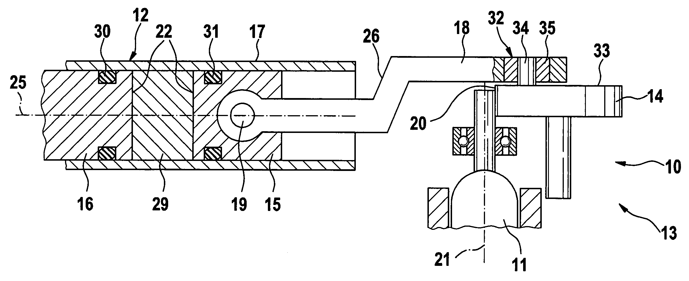
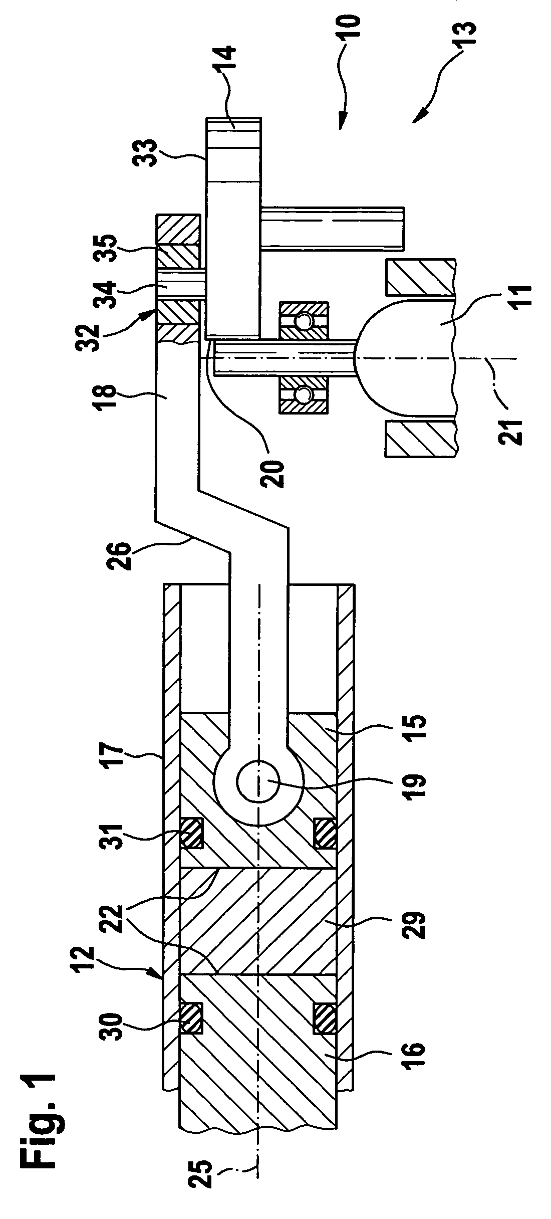
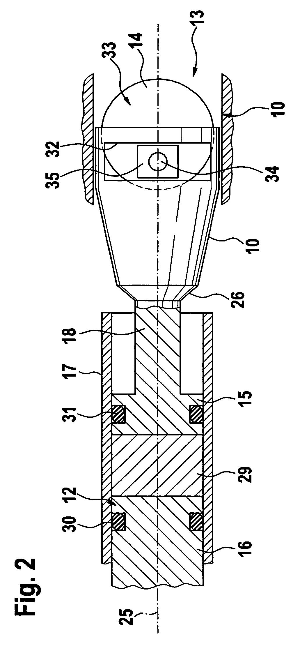
cam driven by a drive unit and an impact mechanism with moving parts; at least two of the moving parts are able to move inside a separate guide cylinder that is stationary in relation to the moving parts and the cam. In particular, a piston and a striker can be provided as the moving parts; the piston that can be moved by the drive unit is able to actuate the striker in a known fashion via an air cushion. The piston and striker can suitably have the same diameter. An electric hammer designed in such a way has a quality equivalent to the known electric hammers with different impact mechanisms.
[0006]Preferably, the piston is connected to the drive unit via a drive element. The embodiment according to the present invention advantageously permits the length of the electric power tool to be shortened. It is thus possible not only for a new designer aspect to be taken into consideration, but also primarily to achieve a slim contour of the electric power tool, as a result of which it is simultaneously also possible to shift the center of gravity and improve the safety of the unit's handling.
[0007]Preferably, the piston and the drive element are connected to each other by means of a pin. In a preferred embodiment form, a pin axis of the pin and the rotation axis of the drive unit can be oriented at an angle in relation to each other, for example of 90°. It is also possible for the piston and the drive element to be embodied as integrally joined to each other.
[0008]In a modification of the present invention, it is possible to adjust an angle between a longitudinal axis of the impact mechanism and a rotation axis of the drive unit. If the drive element is embodied in the form of a cranked rod, then it is advantageously possible to vary an angle between the longitudinal axis of the impact mechanism and the rotation axis of the drive unit. This permits achievement of a new designer-based construction. In addition, this permits an advantageous shifting of the center of gravity in that the drive unit is situated centrally in relation to a longitudinal span of the handle. This permits a reduction of a height of the unit, which has a favorable effect on the weight distribution in the unit and consequently on its handling. On the whole, the embodiment according to the present invention makes it possible to achieve an elongated, more symmetrical form in comparison to the known electric hammers.
[0009]In one embodiment form of the present invention, the drive element can be at least partially comprised of plastic. This advantageously permits a lightweight construction, which in turn makes a positive contribution to an easier, safe operability.
[0010]In order to transmit force between the cam and the drive element, it is possible for a slider crank to be provided. In an above-described cranked embodiment form of the drive element, the slider crank is laterally offset in relation to a longitudinal span of the drive element, which in turn permits advantageous variations in the construction of the unit, making use of new designer aspects. If the slider crank is made of plastic, then it is advantageously possible to prevent a premature deflection of the slider crank due to the above-explained high friction forces. This results in a longer service life of the slider crank and thus represents an advantageous cost savings. To further avoid premature wear, a ball is able to move inside the slider crank.
[0011]It is also possible for a connecting link to be provided for the transmission of force between the cam and the drive element. It is possible for a sliding block to be provided between the eccentric pin and the connecting link, thus advantageously preventing or reducing an undesirable friction. In lieu of the sliding block, it is also possible to embody a different intermediate element that functions in the same manner. The connecting link is preferably embodied as straight. It can, however, also have a different form.
[0012]In an alternative embodiment form, the impact mechanism is embodied with a pot-type striker. Alternatively, an impact mechanism can be embodied with a pot-type piston, which is able to activate a pot-type striker. To reduce the weight of the structure, the pot-type piston is preferably comprised of a light alloy. Alternatively, the pot-type piston can also be made of plastic or of a light alloy / plastic composite. This material composition gives the unit a particularly long service life.

Problems solved by technology

The quality of such electric hammers is not always satisfactory.
The crank pin in particular is subjected to an unsatisfactory bearing friction because of the slider crank.
A movement conversion by means of the connecting link basically corresponds to that of the slider crank, but the design is less favorable.
Primarily, the designer aspect of the known electric hammers is not taken into sufficient consideration.

Method used


Image

  • Electric Power Tool
  • Electric Power Tool
  • Electric Power Tool

Examples


Embodiment Construction

[0017]FIG. 1 is a longitudinal section through an electric hammer, having a drive unit 11 contained in a housing 10, an impact mechanism 12, and a handle 13. The drive unit 11 drives a cam 14; the drive unit 10 and the cam 14 are coupled to each other in a known manner by means of a gearing in the form of a gear-teeth clutch 20. In order to transmit force between the cam 14 and the drive element 18, a connecting link 32 is provided. The rotary motion that the drive unit 11 transmits to the cam 14 is converted by the connecting link 32 into a linear stroke motion of the drive element 18 and is transmitted to an impact mechanism 12.

[0018]The impact mechanism 12 includes two moving parts embodied in the form of a piston 15 and a striker 16, which are able to move inside a separate guide cylinder 17 that is stationary in relation to the moving parts 15, 16. The piston 15 and the striker 16 have the same diameter 22. An annular seal 30 is provided between the piston 15 and the guide cyli...


PUM

PropertyMeasurementUnit
Forceaaaaaaaaaa
Angleaaaaaaaaaa
Diameteraaaaaaaaaa

Abstract

An electric power tool, in particular an electric hammer, having a drive unit (11) contained in a housing (10), an impact mechanism (12), and a handle (13), including a cam (14) that is driven by the drive unit (11); the impact mechanism (12) has moving parts (15, 16).At least two of the moving parts (15, 16) are able to move inside a separate guide cylinder (17) that is stationary in relation to the moving parts (15, 16) and the cam (14).

Description

PRIOR ART[0001]The present invention is based on an electric power tool according to the preamble to claim 1.[0002]Know electric power tools, in particular power hammers, have a drive unit in the form of a wobble pin or connecting rod serving as a drive unit for a hammer piston. Drive units of this kind are known, for example, as crank drives, in which rotary movements of a drive unit, which are transmitted via a crankshaft, are converted into linear movements of the connecting rod. In this case, the drive unit and crankshaft are coupled to each other, in particular by means of a gearing in the form of a gear-tooth clutch. In rotary hammers and percussion hammers, the impact mechanism usually functions on the basis of piston or lever movements that are driven by the connecting rod.[0003]There are also older known electric hammer designs that have a piston drive unit with a slider crank. Slider crank mechanisms are usually comprised of a crankshaft equipped with an eccentrically situ...

Claims


Application Information

Patent Timeline
IPC IPC(8): B25D9/06B25D9/00
CPCB25D11/125B25D2211/003B25D2250/245
Inventor MEIXNER, GERHARDLENNARTZ, JUERGEN
Owner ROBERT BOSCH GMBH
Why Eureka
Try Eureka