

Vehicle brake system
a brake system and vehicle technology, applied in the direction of brake systems, braking components, transportation and packaging, etc., can solve the problems of reducing the service life of the vehicle, increasing the cost of duplicating the power supply system, and imposing cost restrictions
- Summary
- Abstract
- Description
- Claims
- Application Information
AI Technical Summary
Benefits of technology
Problems solved by technology
Method used
Image

Examples
first embodiment
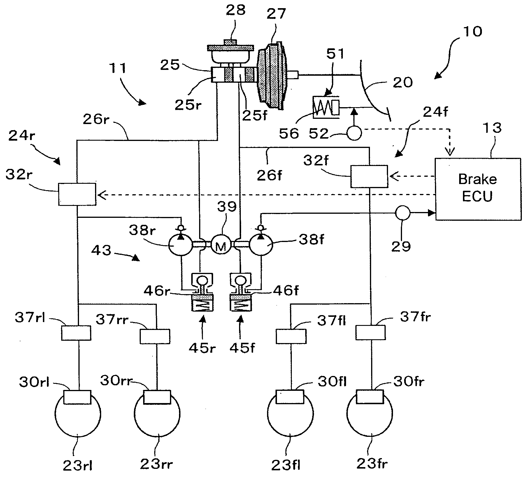
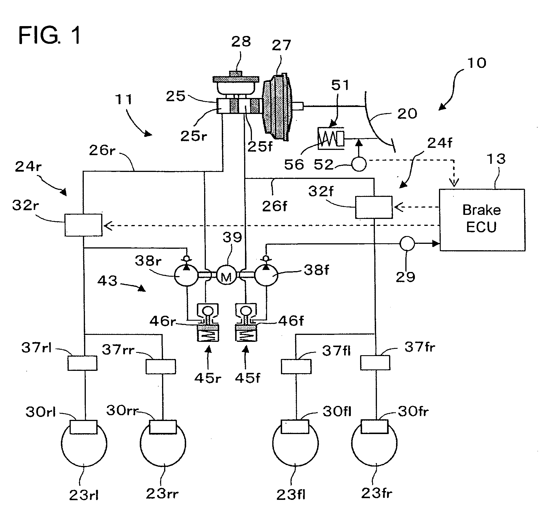
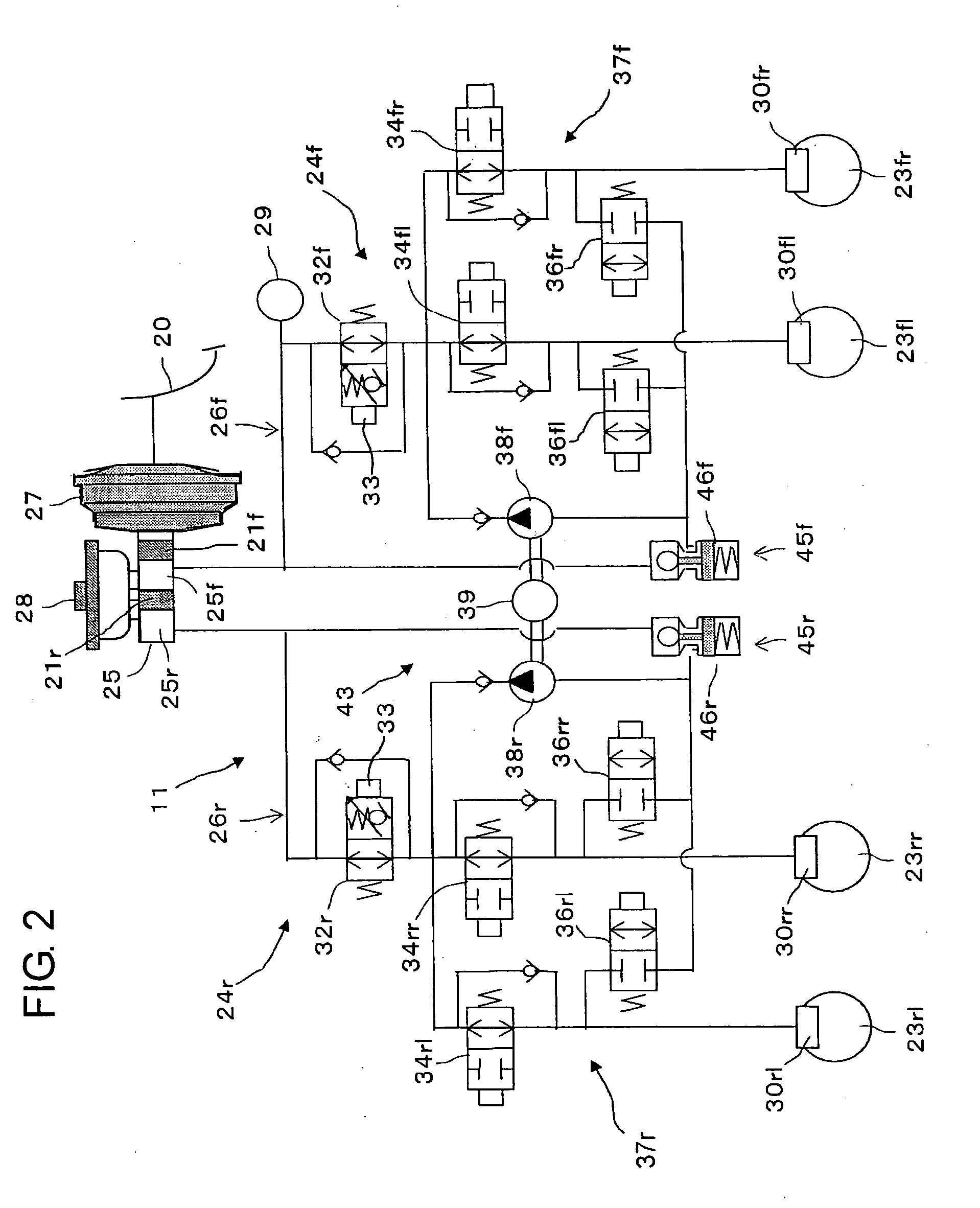
[0030]Hereafter, a vehicle brake system of the brake-by-wire type in a first embodiment according to the present invention will be described with reference to the accompanying drawings. Referring now to FIGS. 1 and 2, the vehicle brake system generally designated by reference numeral 10 comprises a hydraulic brake device 11, an ECU 13 for controlling the hydraulic brake device 11 and the like.
[0031]The hydraulic brake device 11 is provided with left and right front wheel brakes 30fl, 30fr for left and right front wheels 23fl, 23fr and left and right rear wheel brakes 30rl, 30rr for left and right rear wheels 23rl, 23rr. As well-known in the art, each of these brakes 30fl, 30fr and 30rl, 30rr is a disc brake or a drum brake which includes at least one brake cylinder for operating brake shoes to restrict the rotation of a brake disc or drum rotatable with a tire (all not shown). A front wheel brake system 24f for the front wheel brakes 30fl, 30fr and a rear wheel brake system 24r for ...
second embodiment
[0057]FIG. 6 shows some components featuring the vehicle brake system in a second embodiment according to the present invention. The brake system in the second embodiment differs from that in the foregoing first embodiment in that a fluid absorbing mechanism 153 is used instead of the stroke absorbing mechanism 53 composed of the spring 54 and the suspending members 55a, 55b and in that a rubber disc 69 or the like acts to return a reaction force to the brake pedal 20 so that one taking an existing structure can be utilized as the vacuum type booster device27. Therefore, components different from those in the first embodiment will be described hereafter, and components which are identical or same as those in the first embodiment are designated in FIG. 6 by the same reference numerals and will be omitted from being described in detail.
[0058]As shown in FIG. 6, the fluid absorbing mechanism 153 is provided with a bottomed cylinder 57. The bottomed cylinder 57 is connected at one end t...
third embodiment
[0061]FIG. 7 shows a fragmentary circuit featuring the vehicle brake system in a third embodiment according to the present invention. The brake system in the third embodiment only differs from that in the foregoing second embodiment in that a restriction component 70 for restricting the flow of the fluid absorbed by the fluid absorbing mechanism 153 is added on the inlet port side of the fluid absorbing mechanism 153 as the play or idling component. The restriction component 70 is composed of a fixed throttle 71 and a check valve 72 connected in parallel with the fixed throttle 71 for allowing the fluid flow only from the cylinder 57 to the passage 26r.
[0062]In the brake system in the third embodiment, at the time of an abrupt braking manipulation by the driver, the restriction component (the throttle) 70 restrains the quantity of brake fluid flowing into the cylinder 57, and this results in restraining the absorbing speed of the fluid absorbing mechanism 153. It then results that ...
PUM
 Abstract
Description
Claims
Application Information