Inertial switch using fully released and enclosed conductive contact bridge

a contact bridge and fully released technology, applied in the field ofinertial sensors, can solve the problems of large switches, inconvenient operation, and toxic mercury, and achieve the effects of reducing the number of switches

Inactive Publication Date: 2008-10-02
INTEL CORP
View PDF7 Cites 2 Cited by
  • Summary
  • Abstract
  • Description
  • Claims
  • Application Information

AI Technical Summary

Problems solved by technology

Unfortunately, mercury is toxic and containment may be an issue.
Further, such switches are relatively large, and cannot be fabricated by photolithography.
Though it can be made robust, this design has inherent problems.
Eventually, the edge of the anchor may become weak, and break under mechanical stress.

Method used


Image

  • Inertial switch using fully released and enclosed conductive contact bridge
  • Inertial switch using fully released and enclosed conductive contact bridge
  • Inertial switch using fully released and enclosed conductive contact bridge

Examples


Embodiment Construction

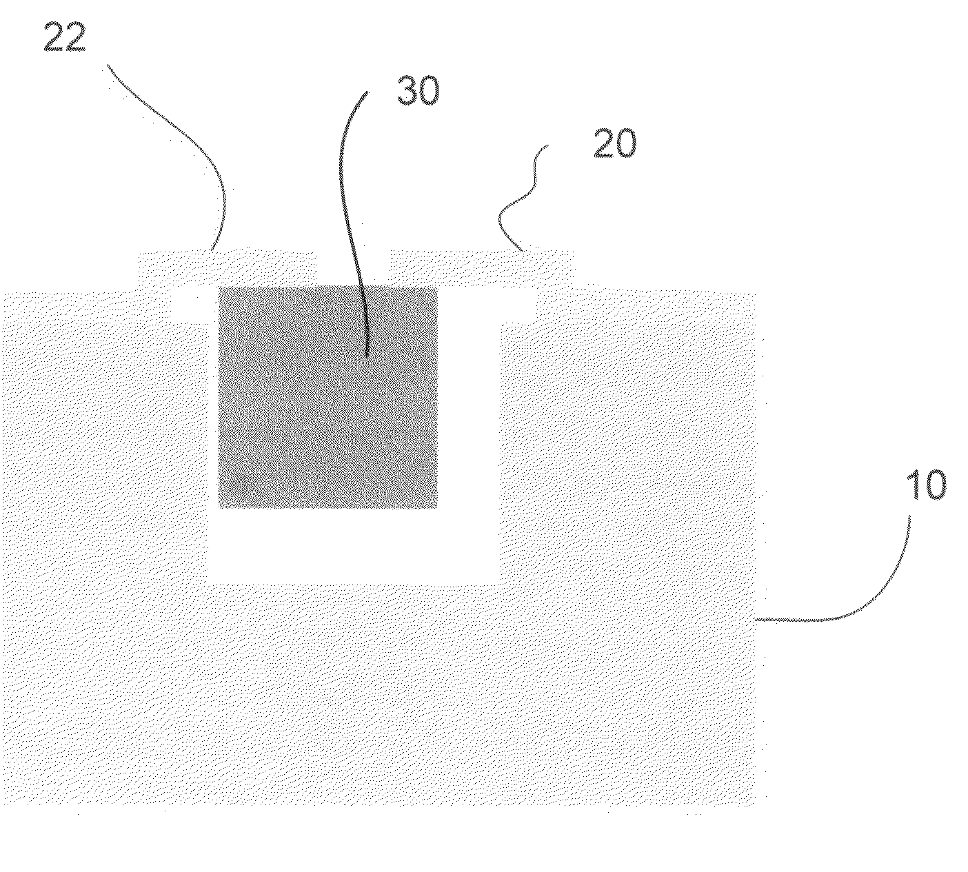
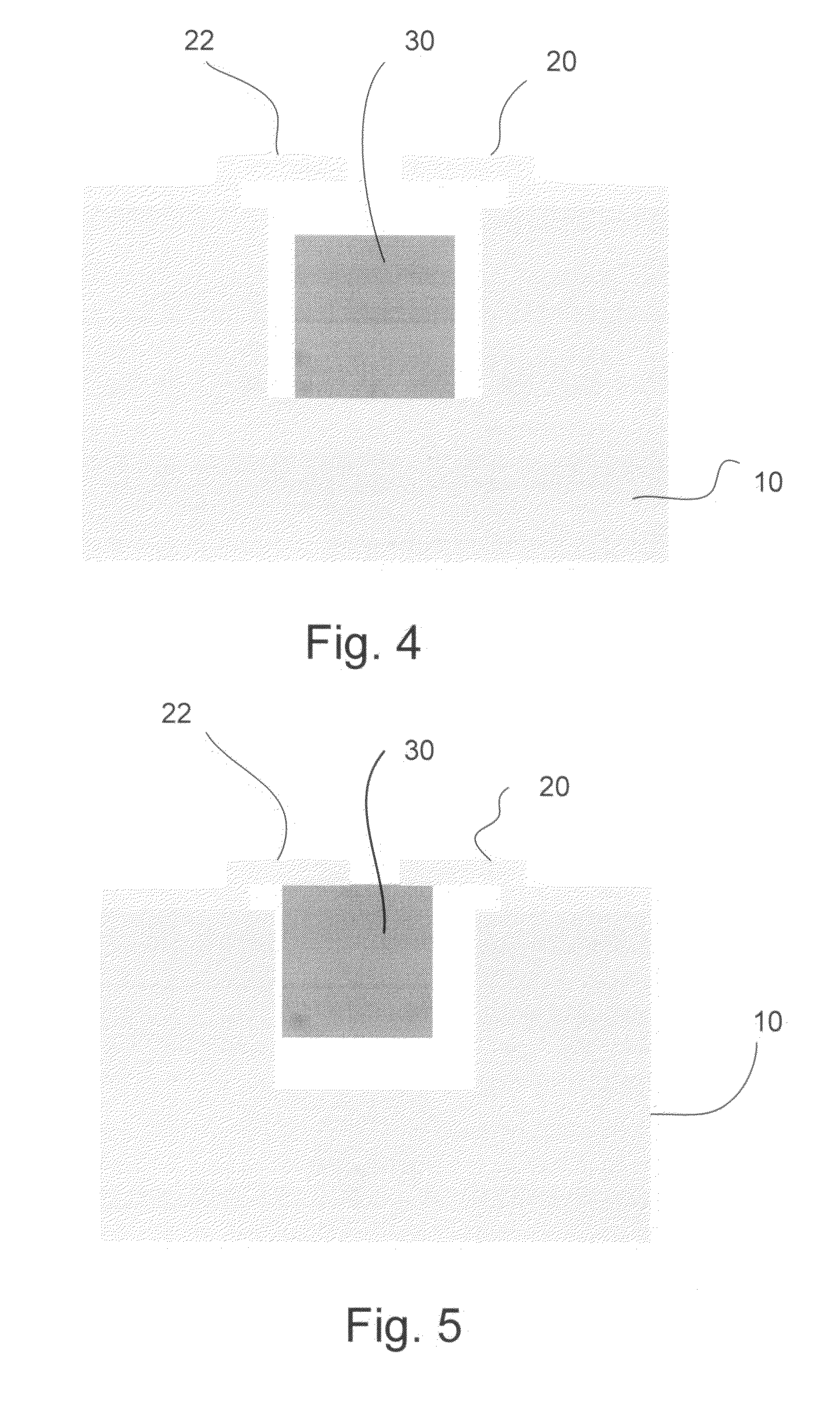
[0010]According to embodiments of the invention, a micro-electromechanical system (MEMS) inertial switch operates using a fully released and enclosed conductive bridging element. A non-anchored conductive mass may be placed inside a cavity within a substrate. Two metal layers are patterned on the substrate so that they are mechanically connected to the substrate, but electrically isolated from the substrate. When inertial forces act in a direction towards the contacts, the conductive mass comes in contact with the electrodes, thus turning the switch “ON”. Conversely, when the forces are directed away from the electrodes, the conductive mass is displaced from its contact position, thus turning the switch “OFF”. Rather than measuring just changes in resistance resulting from changes in mass configuration, changes in capacitance may be measured as well.

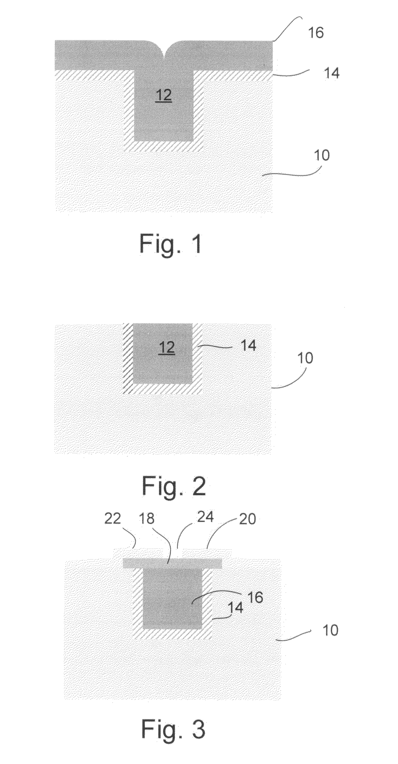
[0011]Referring now to FIG. 1, there is shown a substrate 10, such as, for example silicon. A trench 12 may be formed in the substrate ...


PUM


Abstract

A micro-electromechanical system (MEMS) switch comprises a trench formed in a substrate. A free moving conductive mass may be formed within the cavity. When the switch is moved or otherwise acted upon my an inertial force to conductive mass makes contact with a pair of electrodes partially covering the trench thus turning the switch on.

Description

FIELD OF THE INVENTION[0001]Embodiments of the present invention relate to inertial sensors and, more particularly to micro-electromechanical system (MEMS) switches.BACKGROUND INFORMATION[0002]Inertial sensors, such as accelerometers, have wide applications in many industries. Most notable perhaps being in the aerospace, military, and automotive industries. More recently, they may be found in computer video game controllers where the controller senses user body movements.[0003]One type of traditional accelerometer is the mercury switch. Typically this comprises a sealed tube containing a pair of electrodes and a small amount of mercury. When the tube is tilted or the mercury otherwise accelerated it makes contact with the electrodes and completes an electrical circuit. This may be considered a type of one-bit accelerometer; one bit, because it's either on or off. Unfortunately, mercury is toxic and containment may be an issue. Further, such switches are relatively large, and cannot ...

Claims


Application Information

Patent Timeline
Patent Type & Authority Applications(United States)
IPC IPC(8): H01H35/14
CPCH01H1/0036H01H35/14
Inventor SMITH, JOSHUA R.HECK, JOHNSUNDARA-RAJAN, KISHORE
Owner INTEL CORP
Why Eureka
Try Eureka