
Hydrostatic drive system with variable charge pump

a technology of variable charge pump and drive system, which is applied in the direction of braking system, mechanical equipment, soil shifting machine/dredger, etc., can solve the problems of parasitic power loss, parasitic loss, and overheating of the fluid circulating in the loop under heavy load conditions

Inactive Publication Date: 2008-10-02
CATERPILLAR INC
View PDF16 Cites 80 Cited by
  • Summary
  • Abstract
  • Description
  • Claims
  • Application Information

AI Technical Summary

Benefits of technology

[0010]The closed loop hydraulic system of the present disclosure solves one or more of the problems set forth above.

Problems solved by technology

Although closed loop hydraulic circuits can efficiently control the steering of traction devices, they may be problematic.
In addition, because the hydraulic circuit is closed, fluid circulating in the loop can overheat under heavy load conditions.
Parasitic power losses are a concern with all hydraulic systems including closed-loop circuits having charge pumps.
A major contributor to such parasitic losses is the wasted hydraulic power of the charge flow being throttled across a relief valve.
In addition, fixed displacement pumps are often oversized to account for reduced performance due to wear.
This can lead to parasitic losses in idle and other conditions.
Although the system in the '977 registration does reduce parasitic losses of a pressure system, it still may be suboptimal.
Excess charge flow in low demand situations such as idling conditions can contribute to parasitic losses, even when little or no throttling occurs.
Because the charge system flow remains unchanged, the system of the '977 registration can still incur an unacceptable level of parasitic loss.
Furthermore, the system in the '977 registration may be complex and expensive.
The use of additional components add to the complexity of the system and can increase system cost.
Furthermore, using additional components increases the probability of system failure due to the break down of a component.

Method used


Image

  • Hydrostatic drive system with variable charge pump
  • Hydrostatic drive system with variable charge pump
  • Hydrostatic drive system with variable charge pump

Examples


Embodiment Construction

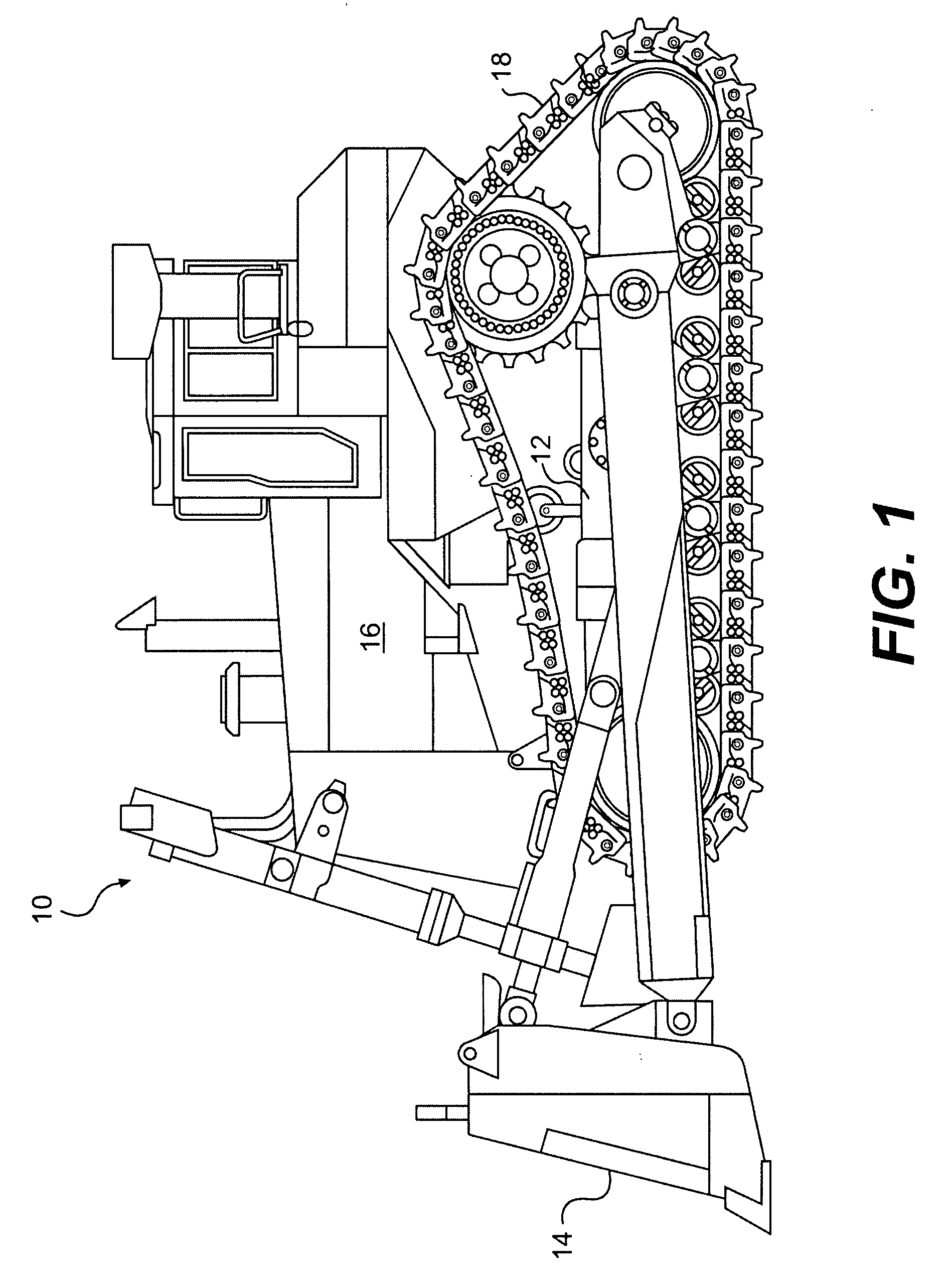
[0016]FIG. 1 illustrates an exemplary machine 10. Machine 10 may be a mobile machine that performs some type of operation associated with an industry such as mining, construction, farming, transportation, or any other industry known in the art. For example, machine 10 may embody the track-type tractor depicted in FIG. 1, a hydraulic excavator, a skid steer loader, an agricultural tractor, a wheel loader, a motor grader, a backhoe, or any other machine known in the art. Machine 10 may include a frame 12, at least one work implement 14, a power source 16, and at least one traction device 18.

[0017]Frame 12 may include any structural unit that supports movement of machine 10 and / or work implement 14. Frame 12 may be, for example, a stationary base frame connecting power source 16 to traction device 18, a movable frame member of a linkage system, or any other frame known in the art.

[0018]Work implement 14 may include any device used in the performance of a task. For example, work impleme...


PUM


Abstract

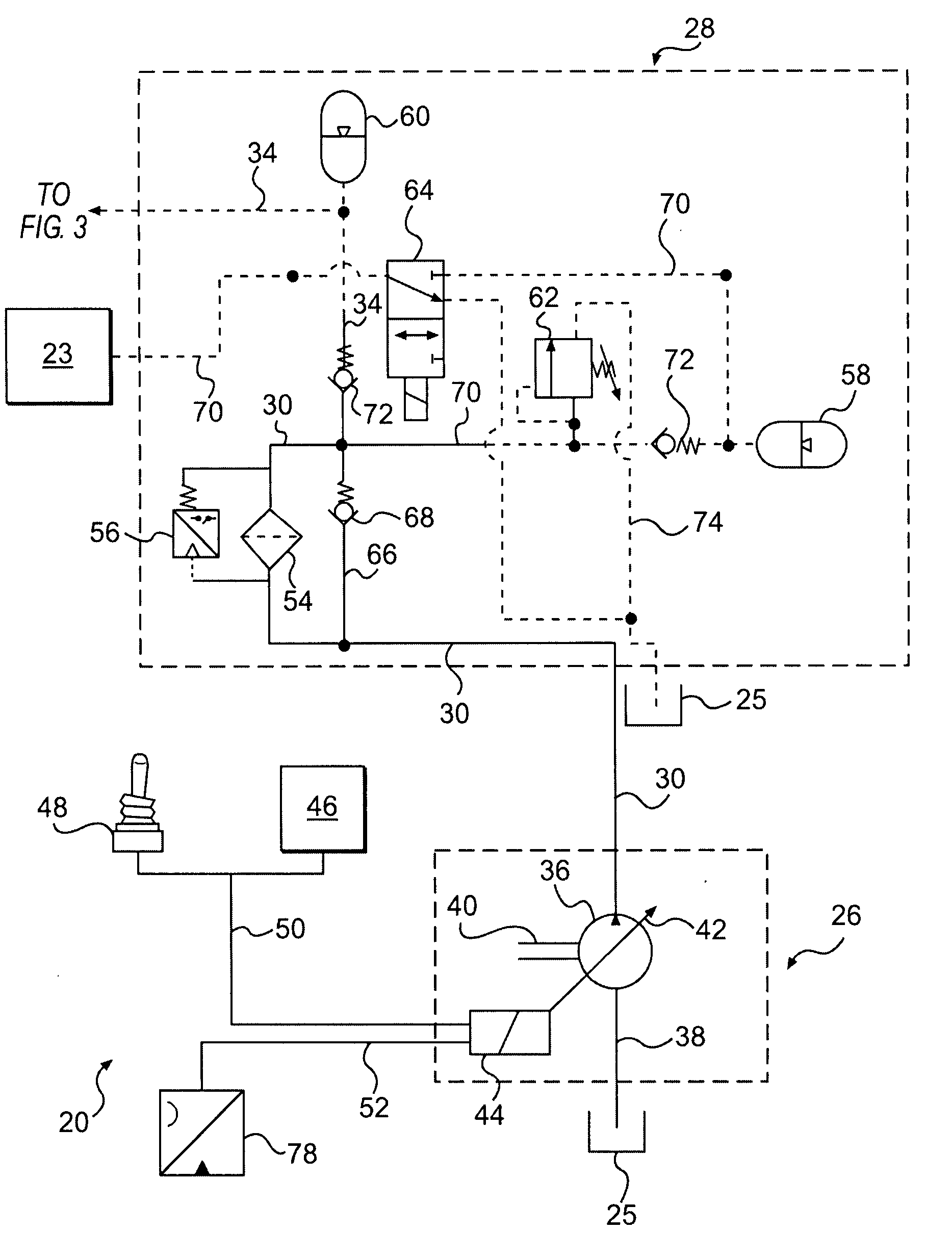
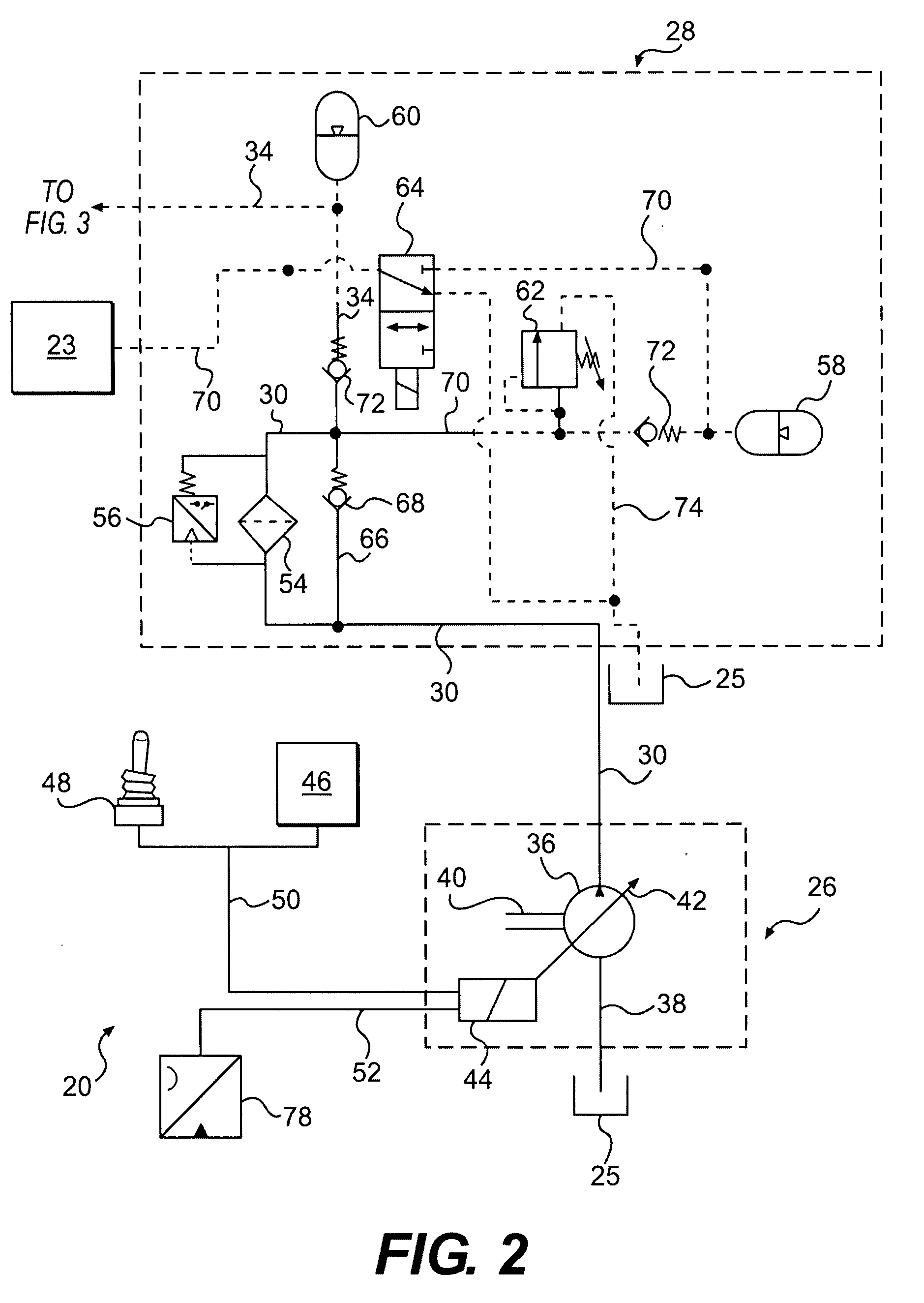
A hydraulic system is provided having a reservoir configured to hold a supply of fluid. The hydraulic system also has a variable displacement pump configured to supply charge fluid and pilot control fluid to the hydraulic system. In addition, the hydraulic system has a closed-loop portion configured to receive charge fluid from the variable displacement pump and drive a mechanism. The hydraulic system further has a pilot fluid supply portion configured to direct pilot control fluid from the variable displacement pump to closed-loop portion.

Description

TECHNICAL FIELD[0001]The present disclosure is directed to a hydrostatic drive system, and more particularly, to a hydrostatic drive system having a variable charge pump providing pressurized make-up and pilot fluid.BACKGROUND[0002]Differential steering systems are commonly used in many types of vehicles, including, for example, those vehicles designed for construction related activities. Each of these vehicles typically includes at least two ground engaging traction devices, which may be, for example, continuous belts, tracks, or tires. The ground engaging traction devices are disposed on opposite sides of the vehicle and may be rotated to propel the vehicle along a chosen path.[0003]A differential steering system guides the vehicle along a chosen path by changing the relative velocity of the ground engaging traction devices. For example, to turn the vehicle to the left, the left ground engaging traction device is rotated at a slower velocity than or in a direction opposite to the ...

Claims


Application Information

Patent Timeline
IPC IPC(8): B60T8/52F16H61/40F16H61/4096F16H61/4139F16H61/42F16H61/433
CPCE02F9/2217E02F9/225E02F9/226E02F9/2296F15B21/005F15B2211/20546F15B2211/25F15B2211/605F15B2211/613F16H61/4096F16H61/4139F16H61/433
Inventor GARNETT, STEPHEN CARLGRICHNIK, MICHAEL JONHARLOW, RANDALL ALANMCINTYRE, DAVID JASONSTEMLER, ERIC DAVIDHAND, TIMOTHY LYNNHENDZEL, ADAMHARKEN, RYAN RAYMONDMCROSTIE, NATHANAEL GARNET
Owner CATERPILLAR INC
Learn More