
Hybrid piezoelectric energy harvesting transducer system

a piezoelectric and transducer technology, applied in piezoelectric/electrostrictive/magnetostrictive devices, piezoelectric/electrostriction/magnetostriction machines, electrical equipment, etc., can solve problems such as system maintenance and reliability, battery-powered systems limit system deployment time, and large wiring from central power sources. achieve the effect of higher electromechanical energy conversion efficiency

Inactive Publication Date: 2008-10-02
NASA +1
View PDF11 Cites 21 Cited by
  • Summary
  • Abstract
  • Description
  • Claims
  • Application Information

AI Technical Summary

Benefits of technology

[0011]It is accordingly the primary object of the present invention to provide what is not available in the art, viz., a hybrid force / stress amplified mechanism having a higher electromechanical energy conversion efficiency than any known piezoelectric transducer.

Problems solved by technology

For a large integrated system such as an aircraft or ship, central electric power can be supplied to sensors and control units at each component; however, wiring from the central power source has been a big burden for these systems, and there have been concerns about system maintenance and reliability.
Advances in various batteries have indeed enhanced the capabilities of many devices; however, the operating lifetime of a battery-powered system limits system deployment time.
However, when pure compliant amplification mechanisms are used, energy waste still exists, indicating that more efficient electromechanical transduction mechanisms should be developed.
Of these, the EAP stack transducers previously reported show significantly high power output; however, net power output is small due to the consumption of the input DC-Bias field to convert the EAP from electric to piezoelectric status.
Piezoelectric transducers with a very high energy conversion efficiency are required in broad variety of advanced technologies, but they are yet unavailable in the art.

Method used


Image

  • Hybrid piezoelectric energy harvesting transducer system
  • Hybrid piezoelectric energy harvesting transducer system
  • Hybrid piezoelectric energy harvesting transducer system

Examples


example 1

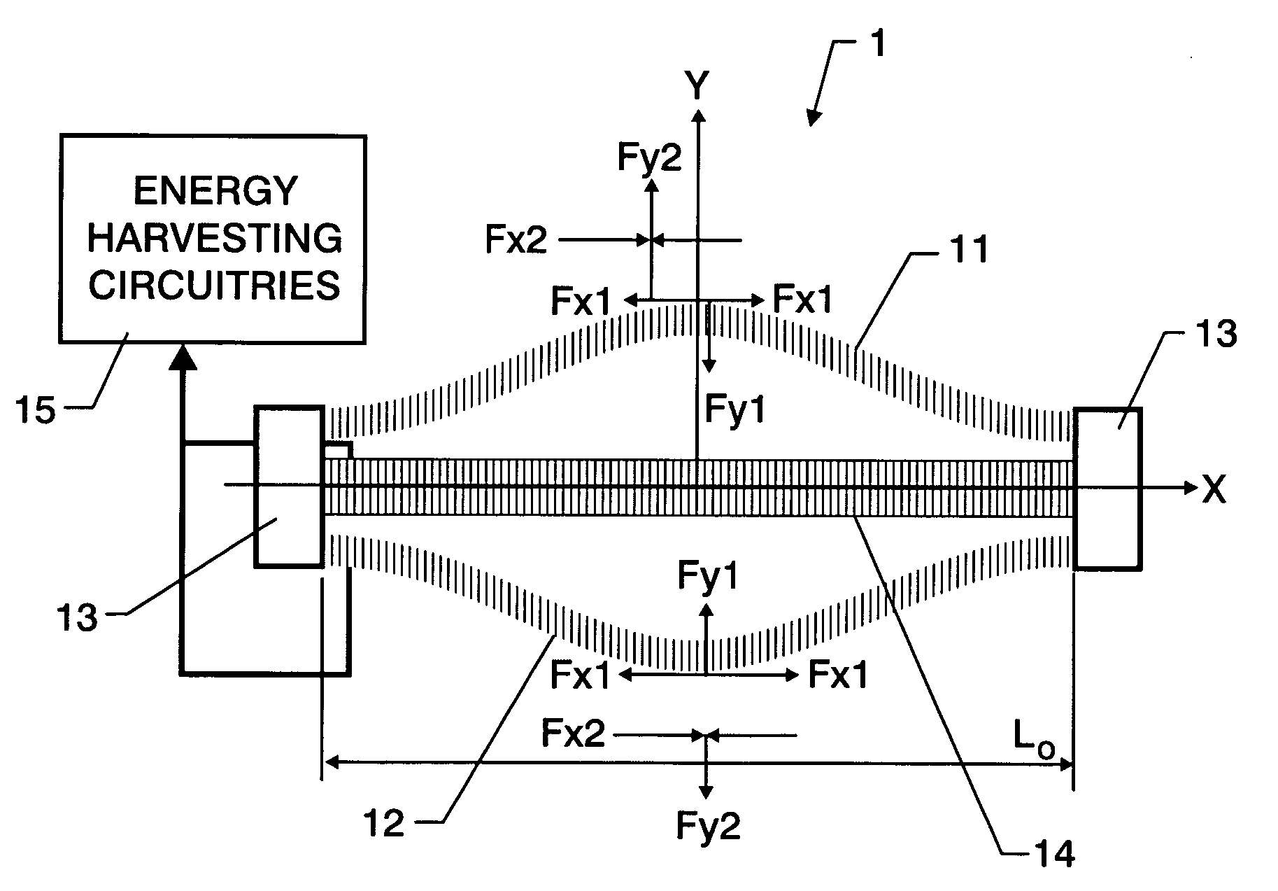
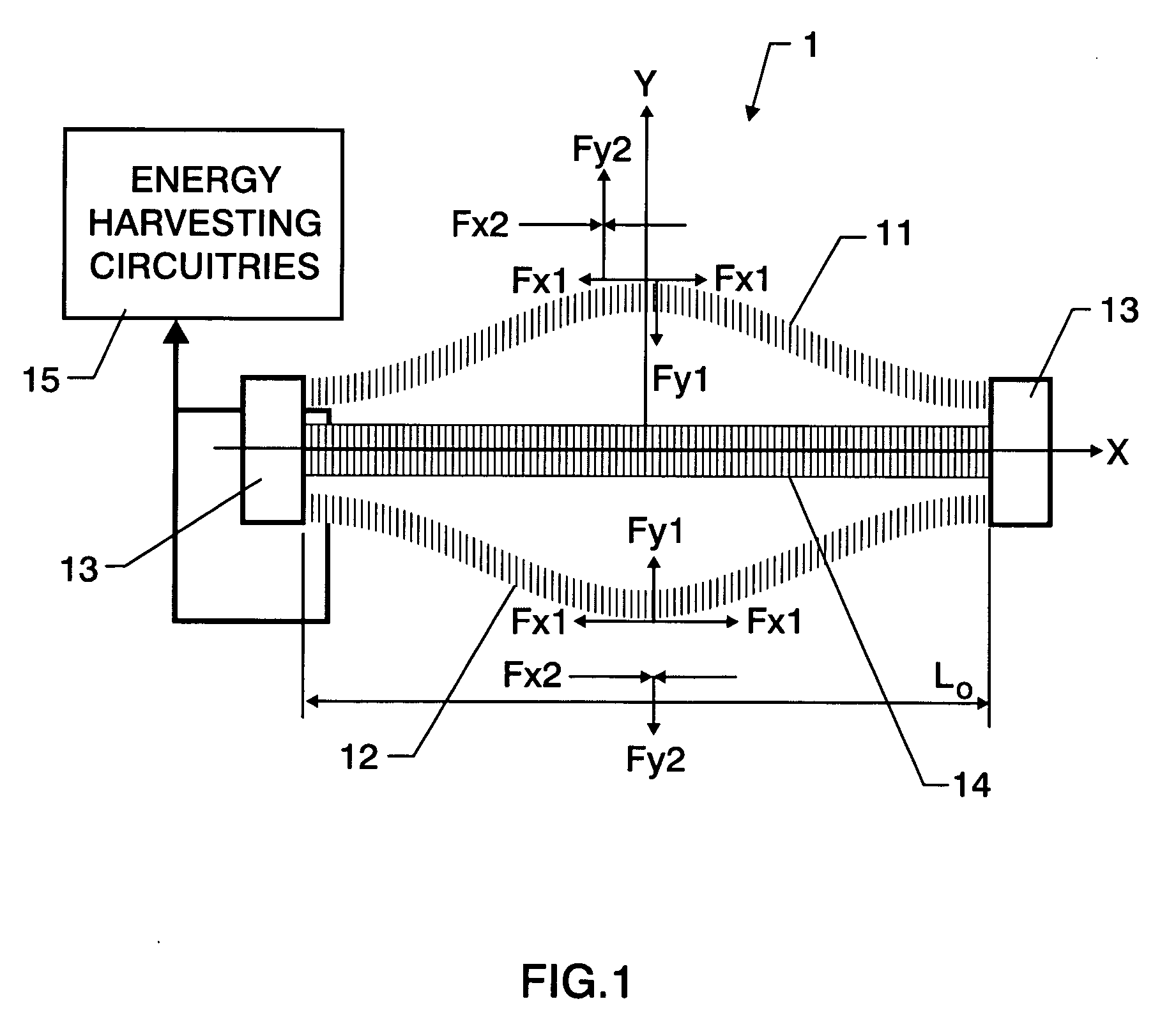
[0049]A piezoelectric single crystal (piezoelectric constant d31=1000 pC / N, d33=2000 pC / N, and dielectric constant ∈=8000) multilayer stack elements-based hybrid force / stress amplified piezoelectric energy harvesting transducer system according to the present invention has the flowing parameters:

Effective length of the transducer:L0 = 10 mmWidth of the transducer:W = 60 mmElement 14:a single layerElement 14 Dimensions:10 mm long4 mm high60 mm wide

[0050]The pre-curved elements 11 and 12 are multilayer stacks (100 layers of 0.1 mm thick single crystal) with dimensions of 10 mm long, 2 mm high, and 60 mm wide. If the force amplification constant is k=100, and applied force, Fy1=80 N, the induced electric energy is 0.3035 (Joules / cycle). If we place 10 elements of this kind of device in each of a soldier's heels, and assume the average weight of a soldier is 80 kg (800 N) and the average walking pace is two steps / second, then the harvested electric energy is 6.07 (Watts) for a normal so...

example 2

[0051]A piezoelectric single crystal (piezoelectric constant d33=2000 pC / N, and dielectric constant ∈=8000) multilayer stack elements-based hybrid force / stress amplified piezoelectric energy harvesting transducer system according to the present invention has the flowing parameters:

Effective length of the transducer:L0 = 10 mmWidth of the transducer:W = 60 mmElement 14:a multilayer stack (100 layersof 0.1 mm-thick single crystal)Element 14 Dimensions:10 mm long4 mm high60 mm wide

The pre-curved elements 11 and 12 are multilayer stacks (100 layers of 0.1 mm thick single crystal) with dimensions of 10 mm long, 2 mm high, and 60 mm wide. If the force amplification constant is k=100, and applied force, Fy1=80 N, the induced electric energy is 0.601 (Joules / cycle). If we place 10 elements of this kind of device in each of a soldier's heels, and assume the average weight of a soldier is 80 kg (800 N), and the average walking pace is two steps / second, then the harvested electric energy is 12...

example 3

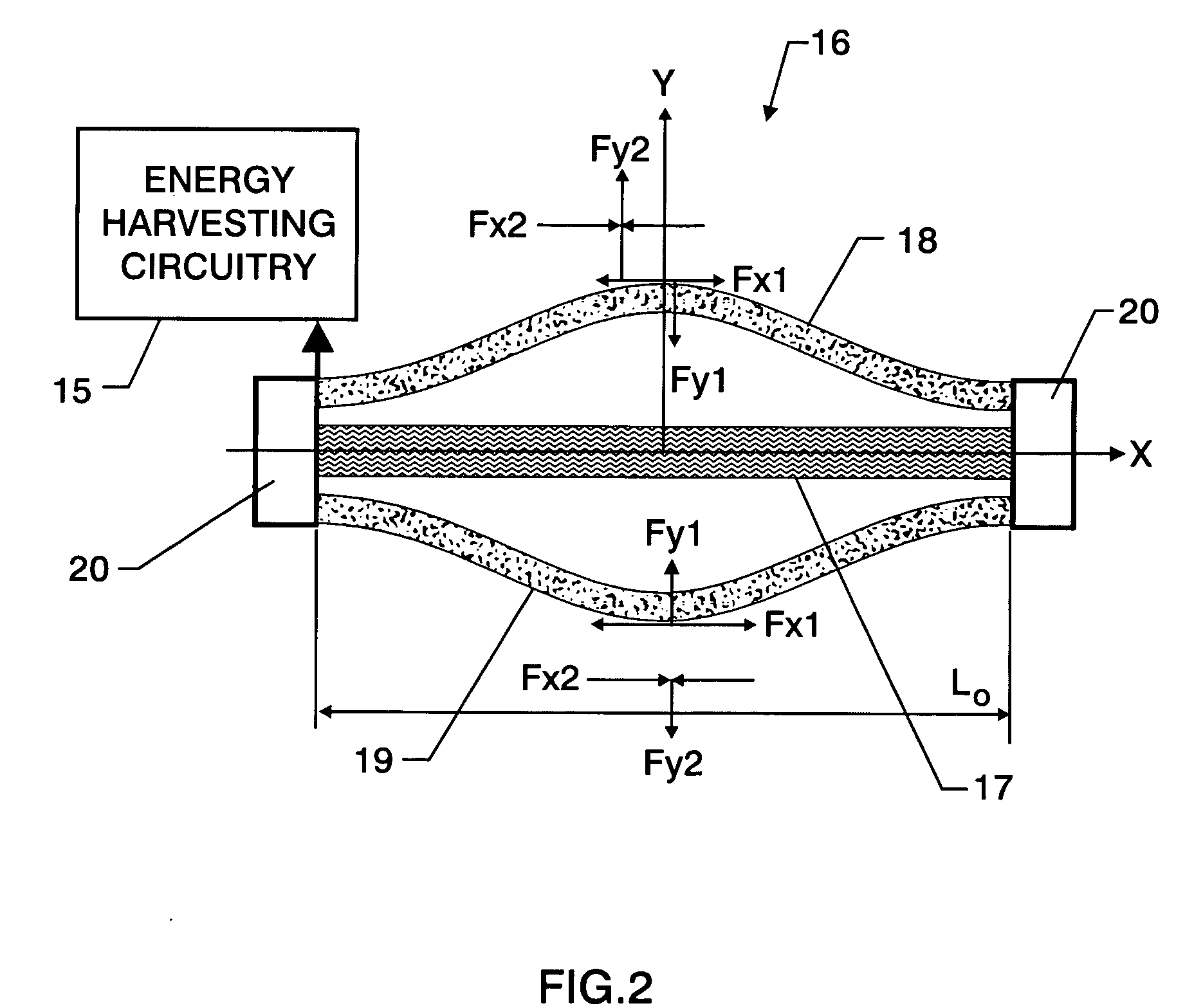
[0052]A piezoelectric PVDF polymer (piezoelectric constant d33=−35 pC / N, dielectric constant ∈=11) multilayer stack elements-based hybrid force / stress amplified piezoelectric energy harvesting transducer system according to the present invention has the flowing parameters.

Effective length of the transducer:L0 = 10 mmWidth of the transducer:W = 60 mmElement 14:a multilayer stack (1000 layersof 0.01 mm-thick single crystal)Element 14 Dimensions:10 mm long4 mm high

60 mm wide

[0053]The pre-curved elements 11 and 12 are multilayer stacks (1000 layers of 0.01 mm thick single crystal) with dimensions of 10 mm long, 2 mm high, and 60 mm wide. If the force amplification constant is k=100, and applied force, Fy1=80 N, the induced electric energy is 0.0308 (Joules / cycle). If we place 10 elements of this kind of device in each of a soldier's heels, and assume the average weight of a soldier is 80 kg (800 N) and the average walking pace is two steps / second, then the harvested electric energy is 0...


PUM


Abstract

A hybrid piezoelectric energy harvesting transducer system includes: (a) first and second symmetric, pre-curved piezoelectric elements mounted separately on a frame so that their concave major surfaces are positioned opposite to each other; and (b) a linear piezoelectric element mounted separately on the frame and positioned between the pre-curved piezoelectric elements. The pre-curved piezoelectric elements and the linear piezoelectric element are spaced from one another and communicate with energy harvesting circuitry having contact points on the frame. The hybrid piezoelectric energy harvesting transducer system has a higher electromechanical energy conversion efficiency than any known piezoelectric transducer.

Description

CROSS-REFERENCE TO RELATED APPLICATION[0001]This application claims the benefit of U.S. Provisional Application No. 60 / 699,106, filed on Jul. 14, 2005 for “Hybrid Force / Stress Amplified Piezoelectric Energy Transducer System”.STATEMENT REGARDING FEDERALLY SPONSORED RESEARCH OR DEVELOPMENT[0002]The U.S. Government has a paid-up license in this invention and the right in limited circumstances to require the patent owner to license others on reasonable terms as provided for by the terms of Cooperative Agreement No. NCC-1-02043 awarded by the National Aeronautics and Space Administration.BACKGROUND OF THE INVENTION[0003]1. Field of the Invention[0004]This invention relates generally to energy harvesting systems. It relates particularly to piezoelectric transducers for the concersion of mechanical energy to electrical energy.[0005]2. Description of Related Art[0006]Mobile computing, communication, and sensing devices have grown significantly in the past decade, as have various sensor net...

Claims


Application Information

Patent Timeline
Patent Type & Authority Applications(United States)
IPC IPC(8): H01L41/113
CPCH01L41/1138H02N2/18H10N30/308
Inventor XU, TIAN-BINGJIANG, XIAONINGSU, JIREHRIG, PAUL W.HACKENBERGER, WESLEY S.
Owner NASA
Learn More