
Method and system for providing scalable and configurable illumination

a technology of configurable illumination and scalable light sources, applied in lighting and heating apparatus, instruments, lighting support devices, etc., can solve the problems that the current light source used in such applications may be one limiting factor on the practicality of imaging modality, or the quality of images that can be obtained, and achieve high energy intensities

Inactive Publication Date: 2008-10-02
GENERAL ELECTRIC CO
View PDF2 Cites 65 Cited by
  • Summary
  • Abstract
  • Description
  • Claims
  • Application Information

AI Technical Summary

Benefits of technology

[0004]The present invention provides an improved light source designed to respond to such needs. The light source may be used in a wide range of applications, particularly where high energy intensities are desired in relatively narrow or reduced areas. The technique is particularly well suited, for example, to medical imaging applications. In general, the invention provides a modular, scalable and configurable incoherent light source.

Problems solved by technology

However, current light sources used in such applications may be one limiting factor on the practicality of the imaging modality, or the quality of the images that can be obtained.

Method used


Image

  • Method and system for providing scalable and configurable illumination
  • Method and system for providing scalable and configurable illumination
  • Method and system for providing scalable and configurable illumination

Examples


Embodiment Construction

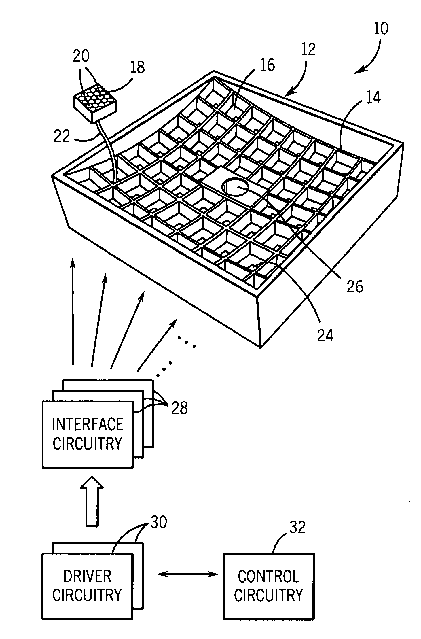
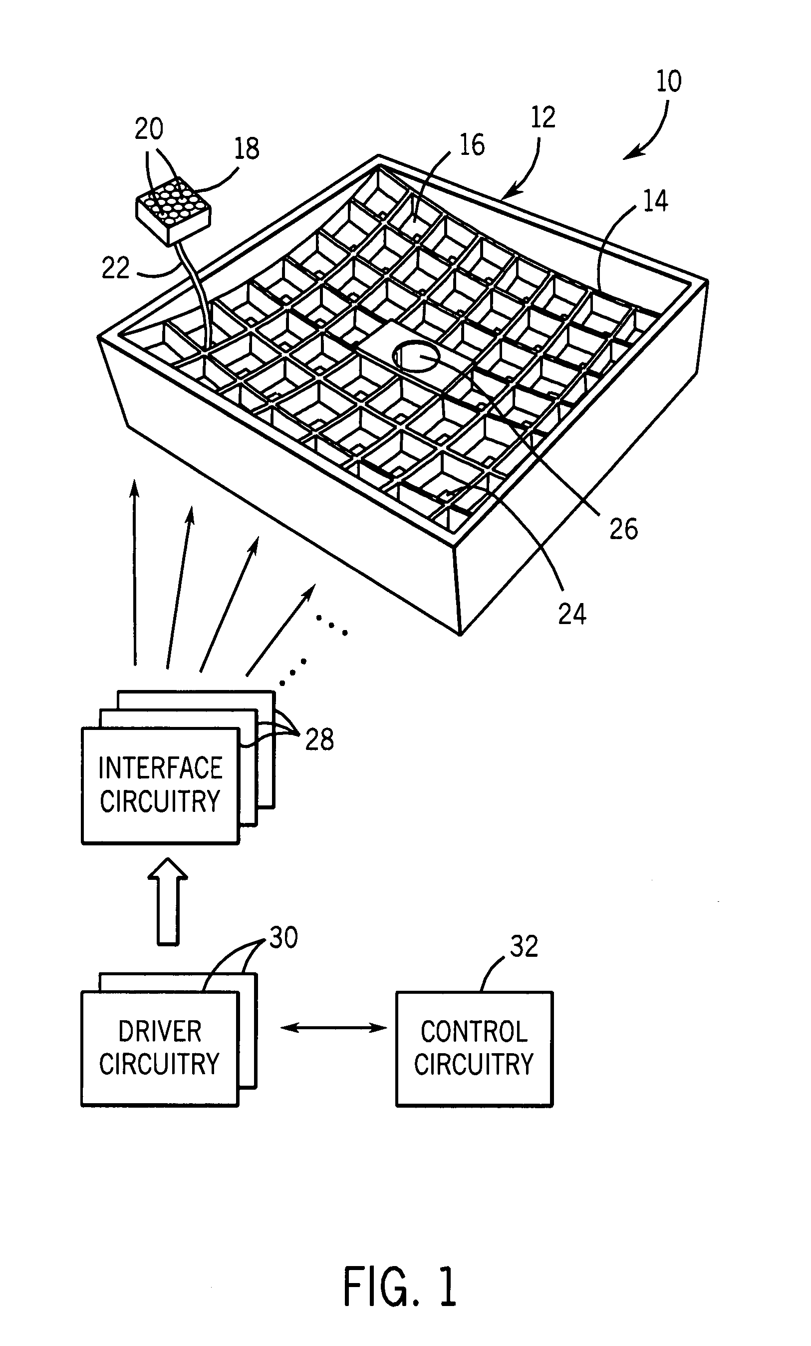
[0019]Turning to the drawings, and referring first to FIG. 1, a light source 10 is illustrated generally, along with the associated circuitry for controlling its operation. The light source is made up of the housing 12 in which a frame 14 is disposed. The housing may be made of any suitable material, such as metal (e.g., aluminum), or a moldable plastic. The frame 14 fits within the housing and is formed to focus light radiation from the light source as described more fully below. In the illustrated embodiment, the frame 14 defines an array of receptacles 16, each of which is designed to accommodate a lighting module, one of which is illustrated in FIG. 1, and designated by the reference numeral 18. As described more fully below, each module may be made up of a plurality of lights, particularly of commercially available LEDs arranged in a tight pattern, as designated in FIG. 1 by reference numeral 20. Each module is supplied with power for illuminating the LEDs by means of a cable 2...


PUM


Abstract

A modular, scalable and configurable incoherent light source is provided. The light source includes an array of lighting modules supported on a frame that focuses emitted radiation from the modules at a region of interest. The geometry and physical configuration of the support structures, including the frame, may accommodate various energy intensities at various distances. The modules may be made up of multiple LEDs or other individual light sources, may be of different or the same wavelength, and may be individually controllable for the ultimate lighting application. The light source may be used in medical imaging applications.

Description

BACKGROUND[0001]The present invention relates generally to the field of lighting sources, particularly bright or high power density sources for applications such as medical imaging, and so forth.[0002]Many applications are known for high power density light sources. Depending upon the particular wavelength desired, light sources may take a number of forms, from conventional light bulbs, to laser light sources, X-ray light sources, and so forth. Within the visible spectrum, light source power density is often limited by the physics of the light source and a reflective or focusing mechanism can be used to concentrate their energy. For example, light bulbs of various types are often associated with reflective surfaces and or reflective lamps that focus their energy in a region of interest. For many light sources, particularly for area lighting, a more diffused emission is desired. However, for high intensity applications new techniques are needed for improved light sources that can pro...

Claims


Application Information

Patent Timeline
IPC IPC(8): H05B37/02F21V21/00F21V9/00
CPCA61B5/0059F21W2131/205F21Y2101/02F21Y2115/10
Inventor LATHAM, STEPHEN ANDREWTAIT, ROBERT WILLIAMLOMNES, STEPHEN JOHNSONPRATT, DUNCAN SPALDINGLESTER, CARL STEPHEN
Owner GENERAL ELECTRIC CO
Learn More