Method for closing used hole on top of gas turbine blade

A technology of gas turbine and blade tip, which is applied in the field of plugging the hole on the gas turbine blade tip and blocking the hole on the gas turbine blade tip, which can solve the problems of melting depth change, cracks in the welded part, uncontrollable plug and bottom plate parts, etc.

Inactive Publication Date: 2004-05-05
MITSUBISHI HEAVY IND LTD
View PDF0 Cites 0 Cited by
  • Summary
  • Abstract
  • Description
  • Claims
  • Application Information

AI Technical Summary

Problems solved by technology

[0007] However, when the tip plug 56 is welded to the hole 55 formed at the tip portion 52 in a TIG welding operation, there is a problem that it is difficult to pre-work the edge for the welding operation because the pre-work of the edge Complicated; welding operation requires job skills and practical experience; and welding operation costs tend to increase
Also, it is not possible to control the plug and bottom plate part ( image 3 The spacing between 55a) in , therefore, there is a problem of changing the melting depth, and more seriously, cracks may occur in the welded part

Method used


Image

  • Method for closing used hole on top of gas turbine blade
  • Method for closing used hole on top of gas turbine blade
  • Method for closing used hole on top of gas turbine blade

Examples


Embodiment

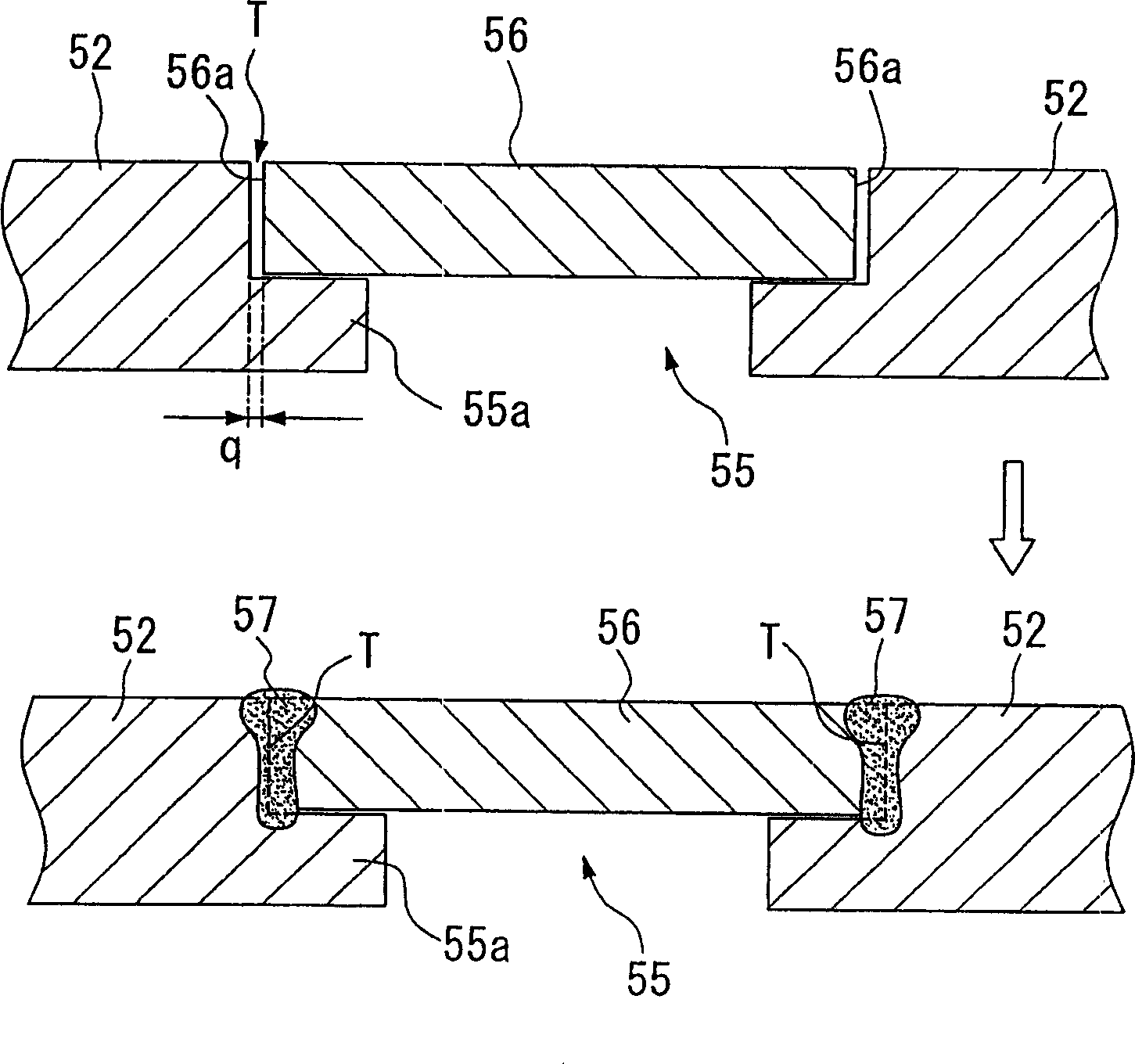
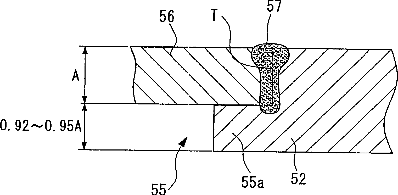
[0074] In an embodiment of the invention, the hole 55 in the tip portion 52 of the turbine blade body 51 formed from the MGA1400DS component is passed through as Figure 7A and 7B The manner shown performs a YAG laser butt welding operation and is plugged by a tip plug 56 made of Inconel 625, a nickel-based superalloy. Should

[0075] The parameters in the examples are as follows.

[0076] (Specification of blade tip part 52)

[0077] Components used to form the tip portion 52: MGA1400DS

[0078] The shape of hole 55: oval

[0079] (parameters of blade tip plug 56)

[0080] Components used to form the tip plug 56: Nickel-based superalloy Inconel 625

[0081] The shape of the blade tip plug 56: oval plate

[0082] A tip plug 56 made according to the above specification is placed on the protruding boss portion 55a of the bore 55 and Figure 7A (plan view) and 7B (side view) were mounted to holes 55 for testing fatigue strength. Also, the laser butt welding operation was...


PUM

PropertyMeasurementUnit
diameteraaaaaaaaaa
diameteraaaaaaaaaa

Abstract

A tip plug 56 is capped on a boss section 55a so as to fit to a hole 55 which is used for detaching a core which is formed in a blade tip section 52 of the gas turbine blade. A butt-section T is melted so as to form a butt-welding section 57 by using a YAG laser beamthere; thus, the hole 55 is plugged by the tip plug 56. Also, parameters such as an interval between the butt-section T, a member for forming the tip plug 56, condition for a laser welding operation, and a defocus position of the laser beam are optimized. By doing this, it is possible to control the entering heat amount and prevent the solidification cracking and the liquation cracking reliably. Furthermore, it is possible to melt and weld the butt-welding section more strongly by using a laser having a narrow bead width; thus, it is possible to improve the manufacturing process efficiently and produce a product in uniform quality repeatedly.

Description

technical field [0001] The invention relates to a method for plugging a hole in a gas turbine blade tip for extracting a core formed inside the blade. The invention relates to a method for plugging a hole in a gas turbine blade tip, wherein the method enables reliable plugging of the hole and the plugging works very efficiently. Background technique [0002] Gas turbine blades are exposed to high temperature operating gases. Therefore, nickel-based superalloys containing relatively large amounts of Al and Ti are generally used to form gas turbine blades in order to improve their creep resistance under high temperature conditions. In addition, to cope with extremely high temperature conditions, it is more common to employ directional solidification and single crystal components in order to adjust the direction of crystal growth in the single crystal components. [0003] On the other hand, a method of making coolant flow in gas turbine blades (hereinafter referred to as turb...

Claims


Application Information

Patent Timeline
Patent Type & Authority Applications(China)
IPC IPC(8): F01D5/28B23K26/14B23K26/21B23K26/28F01D5/14F01D5/18F01D5/20F02C3/05F02C3/30F02C7/00
CPCF02C3/05F01D5/20F05B2230/23F01D5/147B23K26/28B23K26/206F01D5/18F02C3/30F05D2230/23
Inventor 妻鹿雅彦高桥孝二上村好古山口健吾蟹川昌也坪田秀峰藤田宪纲谷俊彦大原稔
Owner MITSUBISHI HEAVY IND LTD
Why Eureka
Try Eureka