Magnetic resonance imaging apparatus and magnetic resonance imaging method

a magnetic resonance imaging and magnetic resonance imaging technology, applied in the direction of reradiation, measurement using nmr, instruments, etc., can solve the problems of difficult to depict relaxation of a spin and the destruction of the phase continuity of a spin, and the difficulty of depicting anatomical structure and lesions

Inactive Publication Date: 2008-10-02
TOSHIBA MEDICAL SYST CORP
View PDF6 Cites 10 Cited by
  • Summary
  • Abstract
  • Description
  • Claims
  • Application Information

AI Technical Summary

Benefits of technology

[0025]The present invention has been made in light of the conventional situations, and it is an object of the present invention to provide a magnetic resonance imaging apparatus and a magnetic resonance imaging method which make it possible to change image contrast by a pulse for a desired object such as labeling, fat-saturation and inversion with keeping phase continuity of spins in imaging under a SSFP sequence.
[0028]The magnetic resonance imaging apparatus and the magnetic resonance imaging method as described above make it possible to change image contrast by a pulse for a desired object such as labeling, fat-saturation and inversion with keeping phase continuity of spins in imaging under a SSFP sequence.

Problems solved by technology

Therefore, when an abdominal image is obtained by a SSFP sequence, there is a case that it is difficult to depict anatomical structure and lesions due to strong fat signal.
In addition, in a preparation block, phase continuity of a spin is destroyed by applying an RF pre-pulse or by applying a spoiler gradient magnetic field pulse.
However, there is a problem that effect due to progression of T1 relaxation of a spin and destruction of phase continuity of a spin is not negligible on tissues each having a short T1 in a living body.
This result caused contrast variation of an image and appearance of an artifact.
Further, the GCFP method has a disadvantage that a radial acquisition cannot be performed since applying direction of a PE gradient magnetic field pulse is limited in the direction perpendicular to a slice.

Method used


Image

  • Magnetic resonance imaging apparatus and magnetic resonance imaging method
  • Magnetic resonance imaging apparatus and magnetic resonance imaging method
  • Magnetic resonance imaging apparatus and magnetic resonance imaging method

Examples


Embodiment Construction

[0044]A magnetic resonance imaging apparatus and a magnetic resonance imaging method according to embodiments of the present invention will be described with reference to the accompanying drawings.

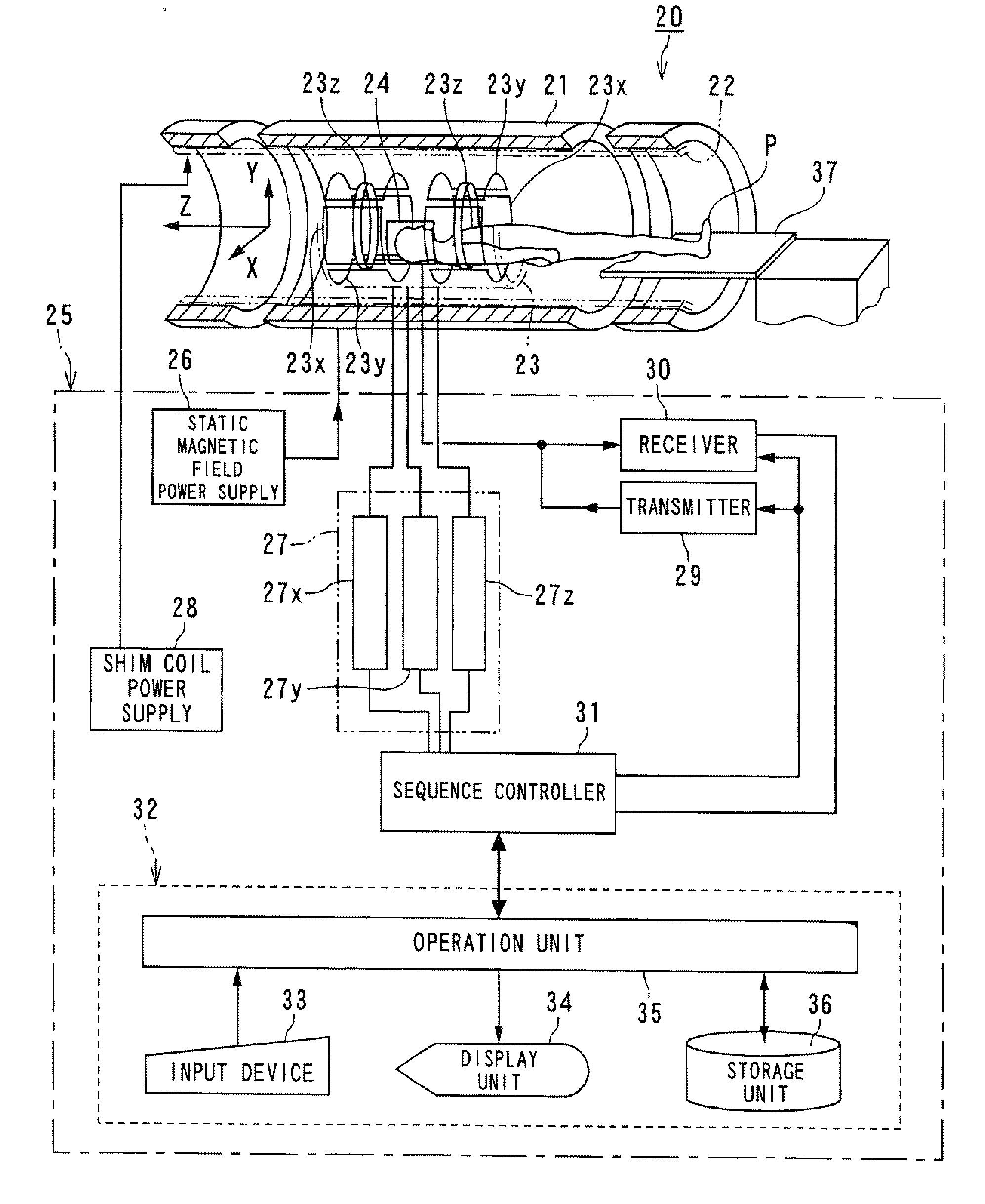
[0045]FIG. 4 is a block diagram showing a magnetic resonance imaging apparatus according to an embodiment of the present invention.

[0046]A magnetic resonance imaging apparatus 20 includes a static field magnet 21 for generating a static magnetic field, a shim coil 22 arranged inside the static field magnet 21 which is cylinder-shaped, a gradient coil 23 and a RF coil 24. The static field magnet 21, the shim coil 22, the gradient coil 23 and the RF coil 24 are built in a gantry (not shown).

[0047]The magnetic resonance imaging apparatus 20 also includes a control system 25. The control system 25 includes a static magnetic field power supply 26, a gradient power supply 27, a shim coil power supply 28, a transmitter 29, a receiver 30, a sequence controller 31 and a computer 32. The gradient po...


PUM


Abstract

A magnetic resonance imaging apparatus includes a data acquisition unit and an image data generating unit. The data acquisition unit acquires data according to a sequence derived by adding a coherent control pulse on a Steady-State Free Precession pulse sequence for repeating plural radio frequency excitations with a constant interval. The coherent control pulse has a center at a substantially center time between adjacent radio frequency excitations and a zero-order moment of which amount is zero. The image data generating unit generates image data based on the data.

Description

BACKGROUND OF THE INVENTION[0001]1. Field of the Invention[0002]The present invention relates to a magnetic resonance imaging apparatus and a magnetic resonance imaging method which excite nuclear spin of an object magnetically with a RF (radio frequency) signal having the Larmor frequency and reconstruct an image based on a MR (magnetic resonance) signal generated due to the excitation, and more particularly, to a magnetic resonance imaging apparatus and a magnetic resonance imaging method which acquire a magnetic resonance image by using SSFP (Steady-State Free Precession).[0003]2. Description of the Related Art[0004]Magnetic Resonance Imaging (MRI) is an imaging method which excite nuclear spin of an object set in a static magnetic field with a RF signal having the Larmor frequency magnetically and reconstruct an image based on a MR signal generated due to the excitation. A magnetic resonance imaging apparatus operates according to a pulse sequence to define an imaging condition....

Claims


Application Information

Patent Timeline
IPC IPC(8): G01R33/54
CPCG01R33/4824G01R33/4828G01R33/4835G01R33/5602G01R33/5607G01R33/5614G01R33/5635G01R33/56366
Inventor YUI, MASAO
Owner TOSHIBA MEDICAL SYST CORP
Why Eureka
Try Eureka