
Probe apparatus, probing method and storage medium

Active Publication Date: 2008-10-02
TOKYO ELECTRON LTD
View PDF5 Cites 11 Cited by
  • Summary
  • Abstract
  • Description
  • Claims
  • Application Information

AI Technical Summary

Benefits of technology

[0023]In accordance with embodiments of the present invention, there is used correction data in which a plurality of reference points on the reference substrate different from the inspection substrate are associated with the correction amounts corresponding to differences in the X, Y and Z directions between the actual contact position and the calculated contact position on the coordinates of the driving system based on the images of the reference points captured by the imaging unit. Accordingly, it is possible to contact the probes with the electrode pads of the chips to be inspected on the inspection substrate while aligning the probes and the electrode pads in a height direction with high accuracy.

Problems solved by technology

In practice, however, it is extremely difficult that the calculated contact position on the coordinates of the driving system coincide with the actual contact position by the effects of processing accuracy of the ball screws, distortion of the ball crews, right-left vibration or forward-backward inclination of a mechanism for guiding movement of the mounting table on an XY plane, inclination around peripheries of the ball screws, and further by the effects of extension and contraction of the ball screws and the like.
Thus, if an overdrive is applied due to the error of the calculated coordinate of the contact position when the probe needles and the contact electrode pads are brought into contact with each other before the original overdrive is applied, the needle tips are already slightly bent at that moment.
Even for the case of vertical needles, a method is considered in which the needle tips thereof are made to slip when the overdrive is applied and the above problems are also encountered.
When an overdrive is already applied in the contact operation, the electrode pads are damaged by the needle tips when the intended over drive is applied.
Accordingly, a large force is applied in a vertical direction to the vertical needles and, hence, the needles are bent, or the probe card becomes crooked.

Method used


Image

  • Probe apparatus, probing method and storage medium
  • Probe apparatus, probing method and storage medium
  • Probe apparatus, probing method and storage medium

Examples


Embodiment Construction

[0045]Hereinafter, embodiments of the present invention will be described with reference to the accompanying drawings which form a part hereof.

[Configuration of Apparatus]

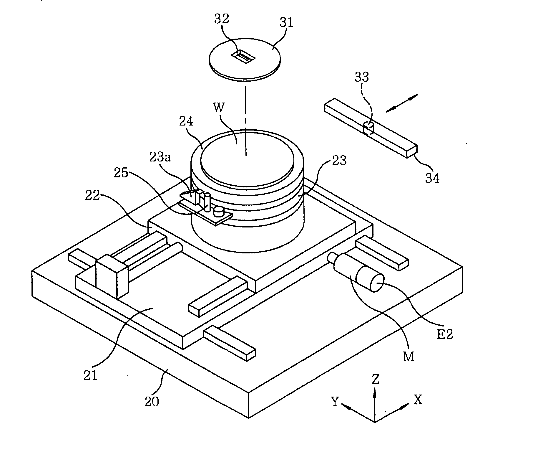
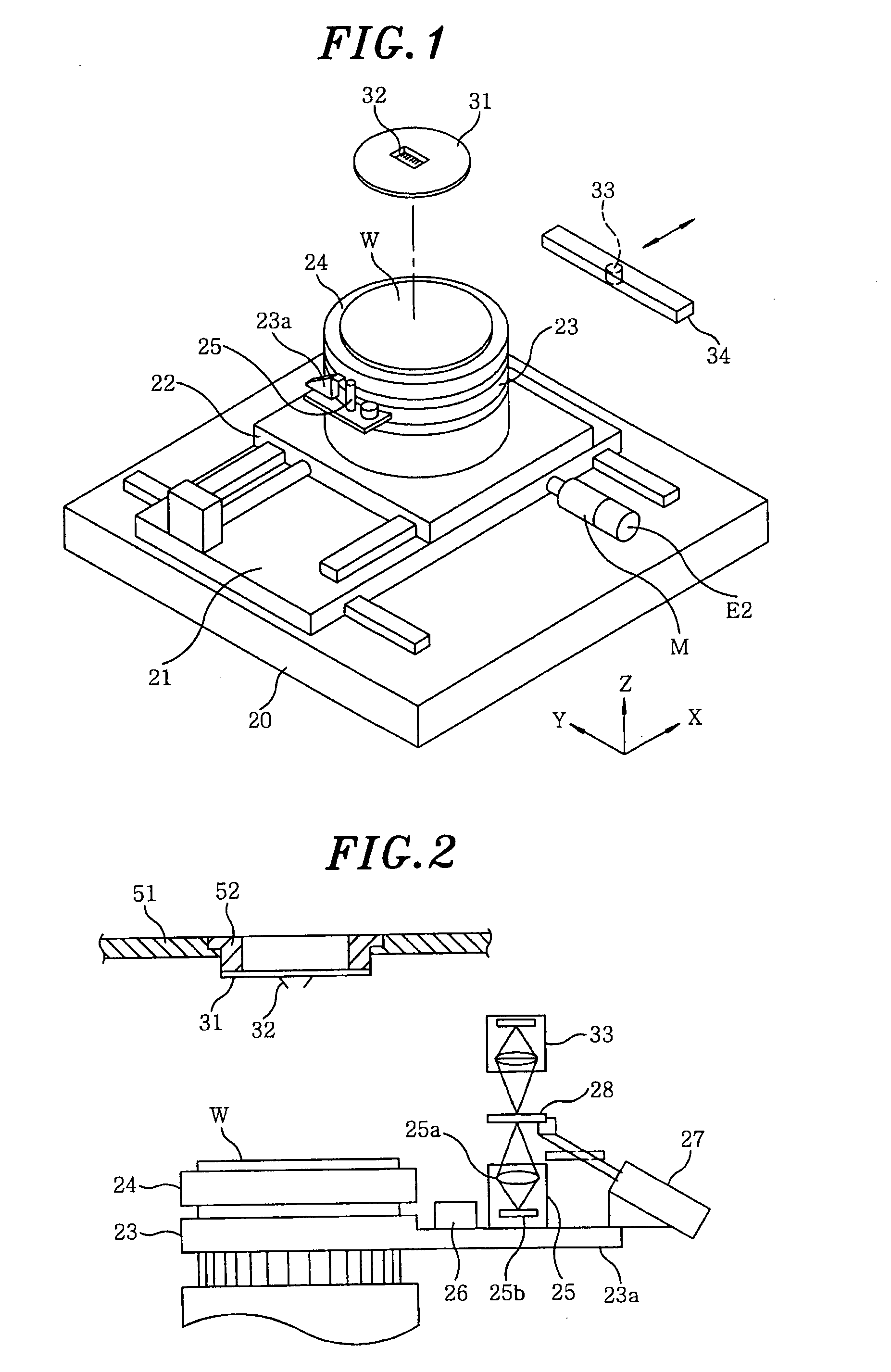
[0046]A probe apparatus 1 used in a probing method of the present invention will be described with reference to FIGS. 1 and 2. The probe apparatus 1 includes a base table 20. Provided on the base table 20 are a Y stage 21 driving in a Y direction by, e.g., ball screws or the like, along a guide rail extending in the Y direction and an X stage 22 driving in an X direction by, e.g., ball screws or the like, along a guide rail extending in the X direction. The X stage 22 and the Y stage 21 are provided with respective motors. A notation M indicates a motor of the X stage 22, and E2 represents an encoder combined with the motor M. However, a motor and an encoder of the Y stage 21 are not shown in FIG. 1.

[0047]Provided on the X stage 22 is a Z moving unit 23 moving in a Z direction by a motor (not shown) combined with a...


PUM


Abstract

A probe apparatus for sequentially testing electrical characteristics of chips includes an imaging unit for capturing images of the electrode pads of the inspection substrate, and a unit for calculating contact positions at which the probes are expected to contact with the electrode pads. The probe apparatus further includes a storage unit for storing correction data in which reference points on a reference substrate are associated with correction amounts corresponding to differences between actual and calculated contact positions of the reference points, and a unit for obtaining actual contact positions for the electrode pads by measuring relative positions of the electrode pads with respect to the reference points and correcting the calculated contact positions of the electrode pads based on the relative positions and the correction data.

Description

FIELD OF THE INVENTION[0001]The present invention relates to a technical field of a probe apparatus for testing electrical characteristics of chips to be inspected while contacting electrode pads of the chips to be inspected with probes of a probe card by moving a mounting table which mounts thereon an inspection substrate on which the chips to be inspected are arranged in column-wise and row-wise.BACKGROUND OF THE INVENTION[0002]After IC chips are formed on a semiconductor wafer (hereinafter, referred to as “wafer”), a probe test is performed on the wafer itself by using a probe apparatus in order to test electrical characteristics of the IC chips. The probe apparatus is constructed to control a position of a mounting table for mounting the wafer thereon capable of moving in X, Y and Z directions and rotating about a Z axis so that probes, e.g., probe needles, of a probe card are brought into contact with electrode pads of the IC chips of the wafer, the probe card being provided ab...

Claims


Application Information

Patent Timeline
IPC IPC(8): G01R1/067
CPCG01R31/2891G01R35/005H01L22/00
Inventor TAKABE, KAZUHIROSUZUKI, MASARU
Owner TOKYO ELECTRON LTD
Learn More