Horn antenna array systems with log dipole feed systems and methods for use thereof

a technology of horn antenna array and log dipole feed system, which is applied in the field of arrays of horn antenna elements, can solve the problems of reducing the efficiency and gain of each element, reducing directivity and beamforming capacity, and mutual coupling between the elements, so as to achieve high gain and directivity

Inactive Publication Date: 2008-10-02
HONG KONG APPLIED SCI & TECH RES INST
View PDF15 Cites 17 Cited by
  • Summary
  • Abstract
  • Description
  • Claims
  • Application Information

AI Technical Summary

Benefits of technology

[0005]Various embodiments of the present invention are directed to a systems and methods which employ horn antenna elements with log dipole feeds. Horn structures with log dipole feeds provide isolation so t

Problems solved by technology

In such systems the phenomena of mutual coupling between the elements is generally an important issue during the design phase.
In multiple antenna systems this typically reduces the efficiency and gain of each element, since some of the energy from each element goes toward the coupling.
Moreover, mutual coupling tends to distort the b

Method used


Image

  • Horn antenna array systems with log dipole feed systems and methods for use thereof
  • Horn antenna array systems with log dipole feed systems and methods for use thereof
  • Horn antenna array systems with log dipole feed systems and methods for use thereof

Examples


Embodiment Construction

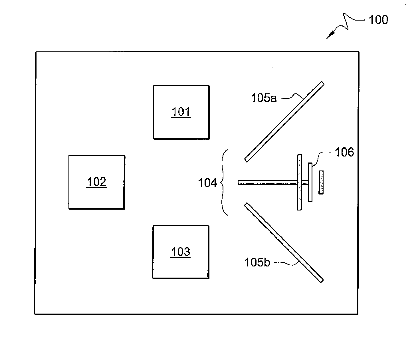
[0022]FIG. 1 is an illustration of exemplary system 100 adapted according to one embodiment of the invention. System 100 is an antenna array with a plurality of antenna elements 101-104. Antenna element 104 includes log dipole feed 106 that is isolated from elements 101-103 by horn structure 105. It is not required that the isolation be absolute, just that some isolation is provided by horn structure 105.

[0023]System 100 has four antenna elements, though other embodiments may include as few as two total elements and may be scaleable up to any number of elements that a design allows. Further, antenna elements 101-103 can, in some embodiments, be the same as or similar in structure to antenna element 104, or may be different. Antenna elements 101-103 are shown to illustrate a plurality of elements, and various embodiments are not limited to the arrangement shown in FIG. 1

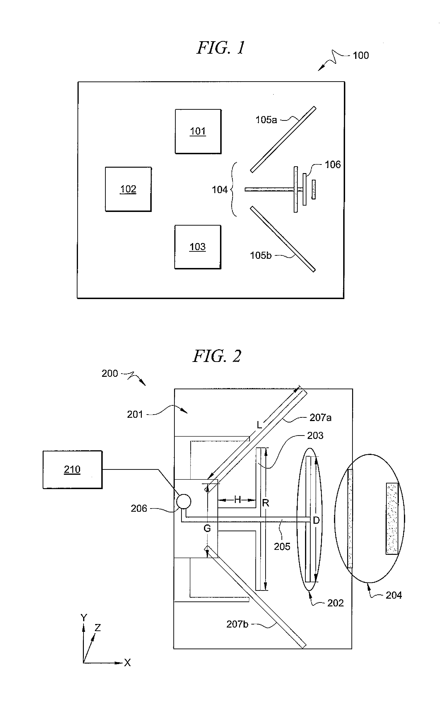
[0024]FIG. 2 is an illustration of exemplary antenna element 200 adapted according to one embodiment of the inventi...


PUM


Abstract

An antenna array comprises a plurality of elements, at least one of the elements including a log dipole isolated from others of the elements by a horn structure.

Description

TECHNICAL FIELD[0001]The description is related to antenna arrays and, specifically, to arrays of horn antenna elements.BACKGROUND OF THE INVENTION[0002]Systems that include multiple antennas are in use in a variety of applications. In such systems the phenomena of mutual coupling between the elements is generally an important issue during the design phase. Mutual coupling occurs when the signal in one antenna element induces signals in other antenna elements. In multiple antenna systems this typically reduces the efficiency and gain of each element, since some of the energy from each element goes toward the coupling. Moreover, mutual coupling tends to distort the beam of each element, thereby reducing directivity and beamforming capacity.[0003]Some prior art systems have attempted to reduce coupling (i.e., increase isolation) between antenna elements in multiple-element-systems. One such technique is to use complex three-dimensional structures similar to Photonic Band Gap (PBG) str...

Claims


Application Information

Patent Timeline
IPC IPC(8): H01Q13/02
CPCH01Q11/10H01Q13/02
Inventor ROWELL, CORBETT R.MAK, ANGUS C.K.
Owner HONG KONG APPLIED SCI & TECH RES INST
Why Eureka
Try Eureka