Eureka AIR delivers breakthrough ideas for toughest innovation challenges, trusted by R&D personnel around the world.

Production spring striper

Inactive Publication Date: 2008-10-02
DELL MARKING
View PDF12 Cites 1 Cited by
  • Summary
  • Abstract
  • Description
  • Claims
  • Application Information

AI Technical Summary

Benefits of technology

[0007]The present invention is directed to one such solution, and particularly is directed to an apparatus that is clean (ink in self contained storage units), allows quick color changes and reduces wasted ink, an application means that does not dry out during short down time periods, keeps up with production rates, effectively meters an appropriate amount of marking media and is cost effective.

Problems solved by technology

A manual system generally utilizes a worker to physically “paint” on a stripe on each spring and is obviously very labor intensive, costly and subject to a higher level of human error.
A very time consuming process.
Down time can be a problem because the application tip typically can dry out in a relatively short time, even as short as during a typical 10-minute break period.
Operators can easily come in contact with the inks and spread the colors over the manufacturing environment, making an undesirable mess.
A high rate of improperly marked or un-marked springs is also a hallmark of the current technology, which can cost significant time and energy in sorting activities.
The state of the art automated systems are cost prohibitive for the smaller manufacturer and has its own set of issues.

Method used


Image

  • Production spring striper
  • Production spring striper
  • Production spring striper

Examples


example

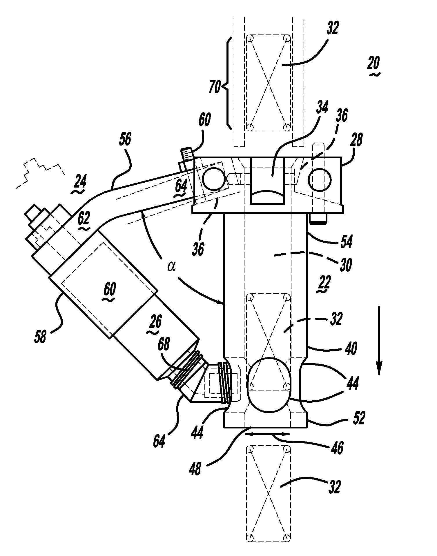
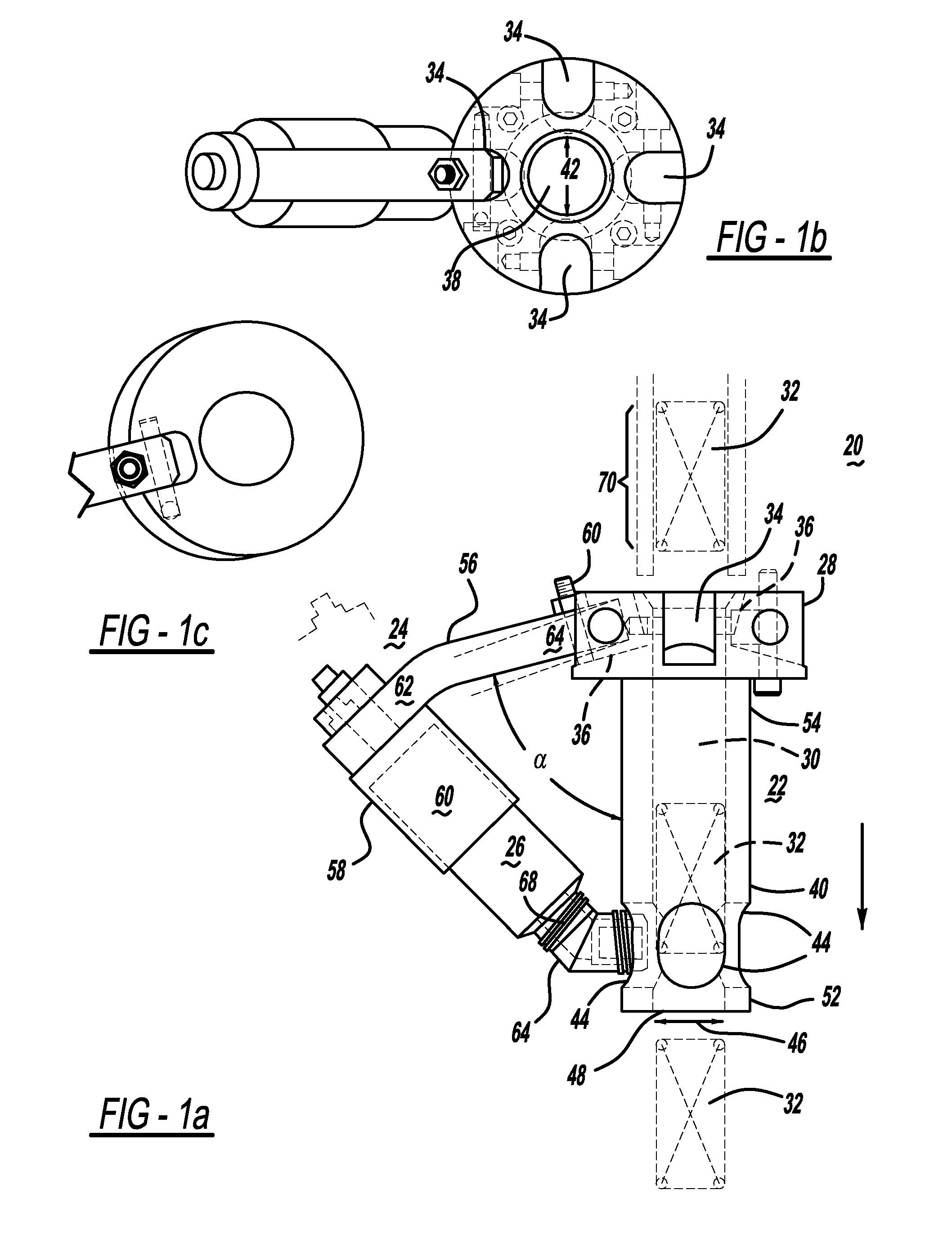
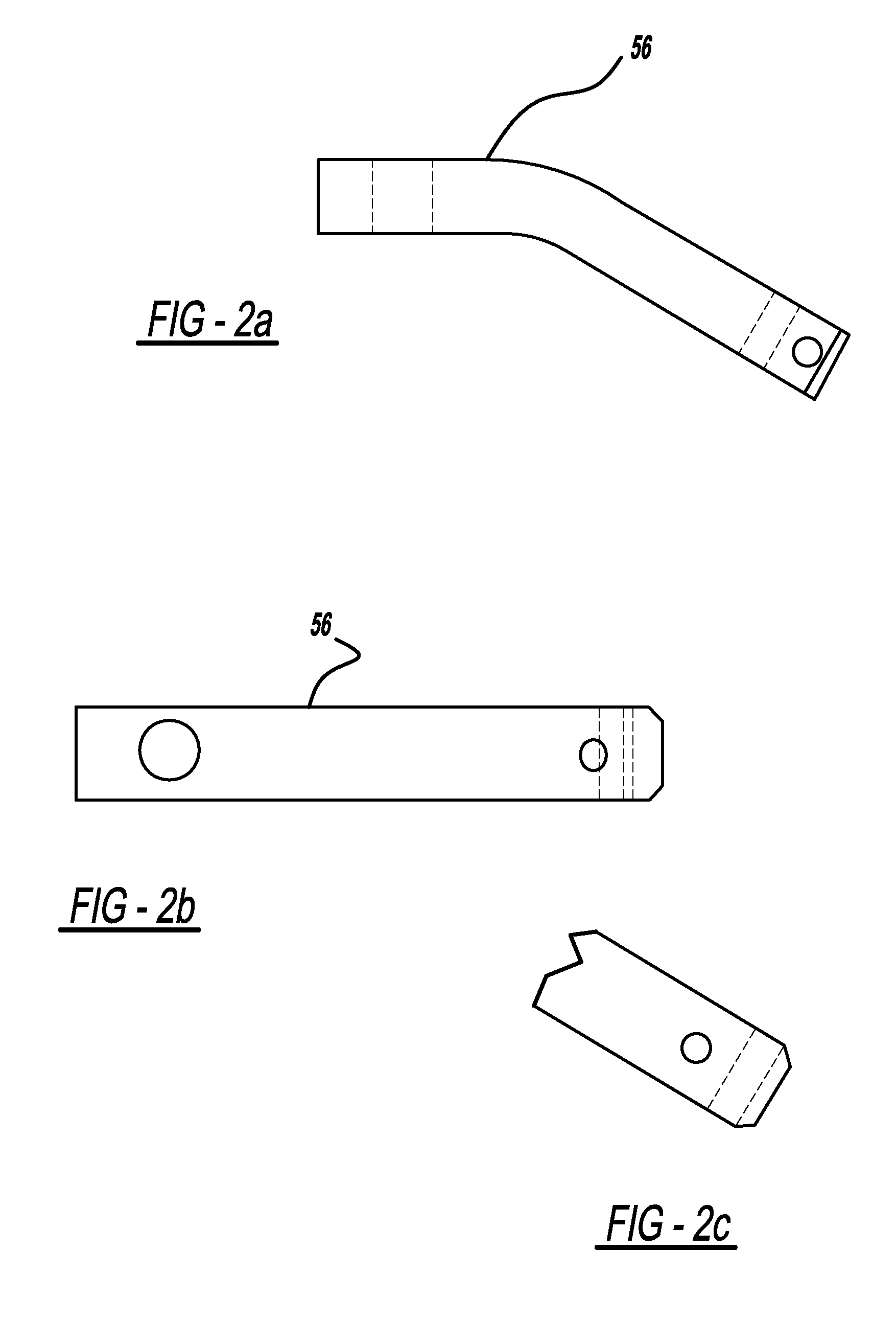
[0022][As an illustrative example, the structure of one embodiment of the inventive self-contained marking apparatus is shown. This example should not be considered limiting as to the scope of the current invention and the relative dimensions of the illustrative marking apparatus can be larger, smaller or both depending on the packaging restraints of the polymeric system being monitored. The structure may be employed for applications beyond the scope of the examples, as taught throughout. One or more of dimensions illustrated likewise may vary by + / −10%, 20%, 30% or higher. Relative proportions even if not specified herein are also contemplated within the present teachings.

[0023]As an illustrative example, as shown in FIG. 1, a spring 32 travels down a production line and through the path 30 in the center of the spring line interface 32. A holding device 24 is balanced on a hinged arm 32. As the spring travels through the interface 32, at least part of the side surface 70 engages th...


PUM


Abstract

The present invention is directed to an apparatus for applying markings, particularly to springs, that are clean (ink in self contained storage units), allows quick color changes and reduces wasted ink or paint. An application means that does not dry out during short down time periods, keeps up with production rates, and is cost effective.

Description

CLAIM OF BENEFIT OF FILING DATE[0001]The present application claims the benefit of the filing date of U.S. Provisional Application Ser. No. 60 / 909,173 filed Mar. 30, 2007, hereby incorporated by reference.FIELD OF THE INVENTION[0002]An apparatus for applying a stripe to a article like in a production line, particularly to a self-contained marking apparatus with a gravity feed system for applying a stripe, stripes or both to a spring.BACKGROUND[0003]It is common practice within industry to place a mark on individual articles (e.g. a stripe to a spring) to identify the article (e.g. the type of spring) that has been produced. In the case of a spring, each type of spring is assigned its own color stripe for identification purposes. This currently is being accomplished via both manual and automated processes, depending on the size and complexity of the manufacturing operation.[0004]A manual system generally utilizes a worker to physically “paint” on a stripe on each spring and is obviou...

Claims


Application Information

Patent Timeline
IPC IPC(8): B41J2/00
CPCB05C1/02
Inventor GRATTAN, MICHAEL A.BROWN, JEFFREYKRIEG, MICHAELDELIDOW, NORTON
Owner DELL MARKING
Why Eureka
Eureka Blog
Learn More